Instructions to learn how to use a lathe
Listen to a podcast about this article
Instructions to Learn How to Use a Lathe
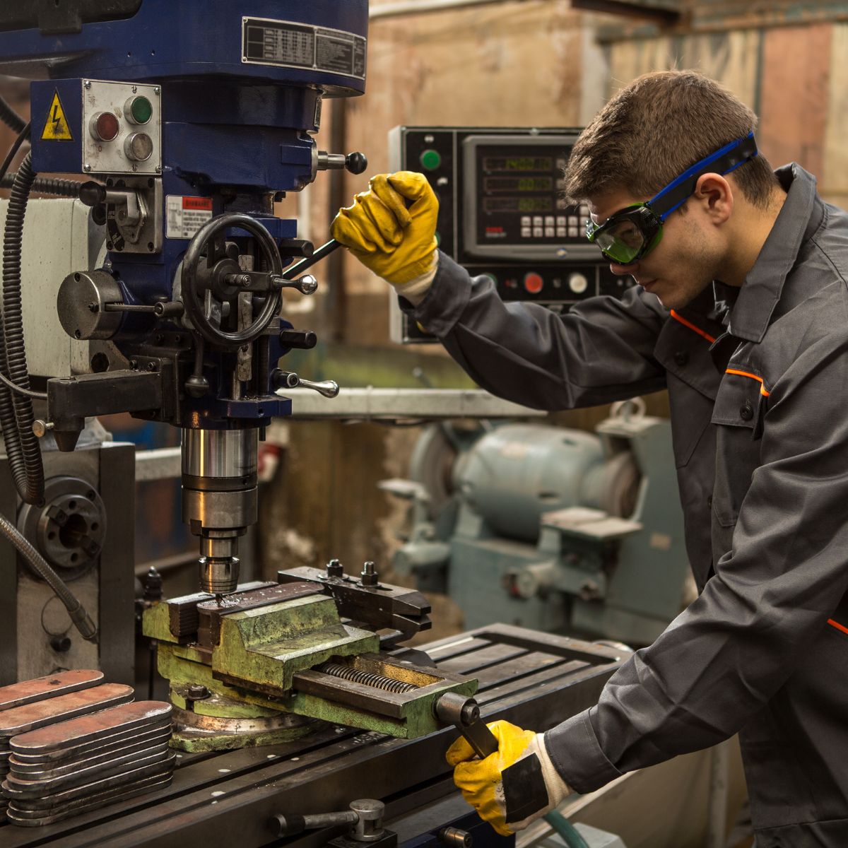
The lathe is a machine tool used principally for shaping pieces of metal (and sometimes wood or other materials) by causing the workpiece to be held and rotated by the lathe whilst a tool bit is advanced into the work causing the cutting action. The basic lathe that was designed to cut cylindrical metal stock has been developed further to produce screw threads, tapered work, drilled holes, knurled surfaces, and crankshafts. Modern lathes offer a variety of rotating speeds and a means to manually and automatically move the cutting tool into the workpiece. Machinists and maintenance shop personnel must be thoroughly familiar with the lathe and its operations to accomplish the repair and fabrication of needed parts.
Types of Lathes
Lathes are generally grouped into three main categories: engine lathes, turret lathes, and special-purpose lathes. Compact versions can be installed on a workbench or moved easily, while large industrial models are fixed to the floor and require careful handling when relocated. In most workshop and maintenance settings, a versatile and moderately sized lathe is preferred for mobility and adaptability. The engine lathe fits this need perfectly, allowing skilled operators to carry out a wide range of machining tasks. In contrast, turret and special-purpose lathes are designed primarily for repetitive, high-volume production or specialised manufacturing. Throughout this guide, any mention of lathes refers specifically to engine-type machines.
Engine Lathes


Lathe Sizes
The size of an engine lathe is defined by the largest workpiece it can accommodate. Before starting any machining job, two key measurements must be checked: the swing over bed, which indicates the maximum diameter that can safely rotate without obstruction, and the distance between centres, which determines the longest piece that can be mounted between the headstock and tailstock.
Lathe Categories
Although engine lathes vary slightly in design from one manufacturer to another, they are generally divided into three main categories: lightweight bench lathes, precision toolroom lathes, and gap or extension-type lathes. Each type serves a specific purpose, bench lathes for smaller, portable work, toolroom lathes for high-accuracy machining, and gap lathes for handling larger or irregular workpieces.
Lightweight
Lightweight bench engine lathes are generally small lathes with a swing of 10 inches or less, mounted to a bench or table top. These lathes can accomplish most machining jobs, but may be limited due to the size of the material that can be turned.
Lathe Precision
Precision tool room lathes are also known as standard manufacturing lathes and are used for all lathe operations, such as turning, boring, drilling, reaming, producing screw threads, taper turning, knurling, and radius forming, and can be adapted for special milling operations with the appropriate fixture. This type of lathe can handle workpieces up to 25 inches in diameter and up to 200 inches long. However, the general size is about a 15-inch swing with 36 to 48 inches between centres. Many tool room lathes are used for special tool and die production due to the high accuracy of the machine.
Gap or Extension-Type Lathes
Gap or extension-type lathes share many similarities with precision toolroom lathes but include an adjustable bed design that allows for machining larger diameters and longer workpieces. By sliding the bed a short distance away from the headstock, typically one or two feet, the operator can increase the swing capacity. This adjustment enables the lathe to handle extra-long workpieces between centres without compromising precision.
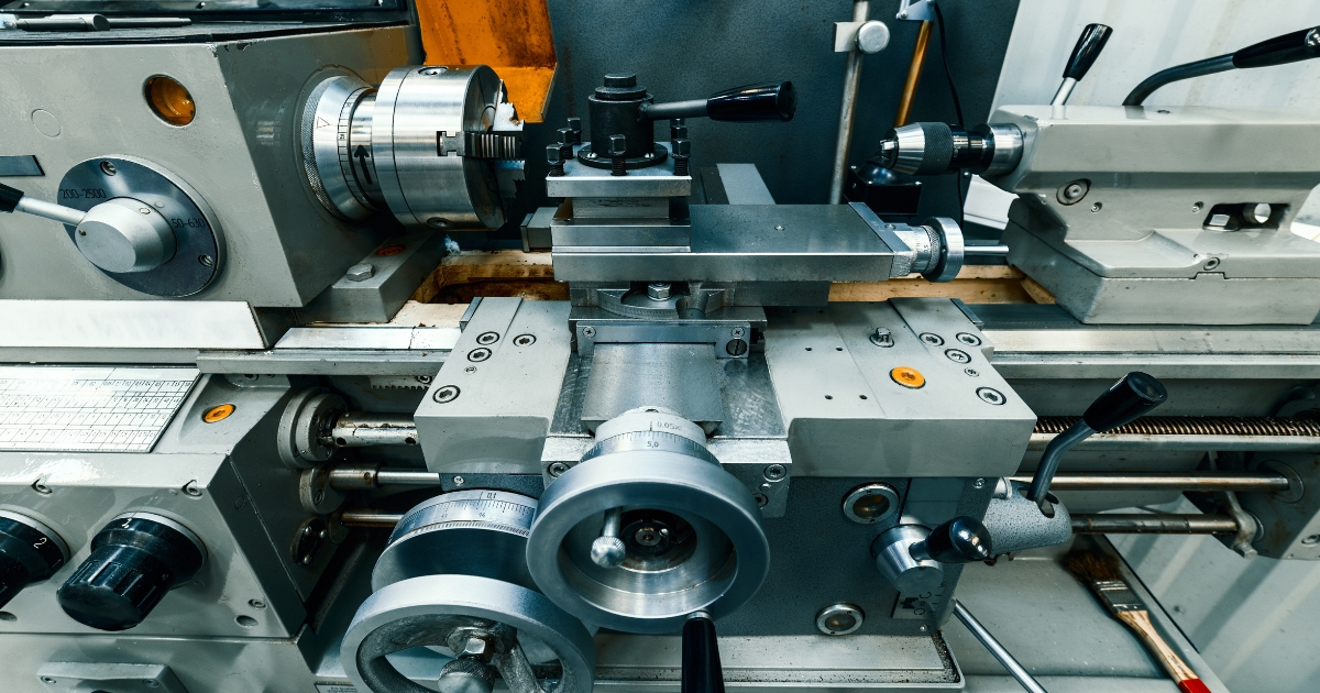
Lathe Components
All engine lathes feature the same essential components, although the placement and design of individual parts may vary between manufacturers. The bed serves as the machine’s foundation, supporting and aligning all other operational elements.
The most important part of the bed’s construction is the set of precision-ground ways that extend along its full length. These ways provide a stable guide for both the tailstock and carriage, ensuring smooth movement and perfect alignment with the headstock during machining operations.
The headstock is located on the operator's left end of the lathe bed. It contains the main spindle and oil reservoir and the gearing mechanism for obtaining various spindle speeds and for transmitting power to the feeding and threading mechanism. The headstock mechanism is driven by an electric motor connected either to a belt or pulley system or to a geared system. The main spindle is mounted on bearings in the headstock and is hardened and specially ground to fit different lathe holding devices. The spindle has a hole through its entire length to accommodate long workpieces. The hole in the nose of the spindle usually has a standard Morse taper which varies with the size of the lathe. Centres, collets, drill chucks, tapered shank drills and reamers may be inserted into the spindle. Chucks, drive plates, and faceplates may be screwed onto the spindle or clamped onto the spindle nose.
The tailstock is positioned opposite the headstock and provides support for one end of the workpiece during machining between centres. It also stabilises long materials held in the chuck and can hold tools such as drills, reamers, and taps. Mounted on the lathe ways, the tailstock can be clamped securely at any point along its travel. Its sliding spindle is controlled by a handwheel and locked in place using a spindle clamp. For alignment adjustments, the tailstock can be shifted laterally (toward or away from the operator) using adjustment screws. Always ensure the tailstock is unclamped before making these adjustments to allow free movement and prevent damage to the alignment screws.
The carriage assembly includes the apron, saddle, compound rest, cross slide, tool post, and cutting tool. Positioned across the ways and in front of the lathe bed, the carriage’s primary function is to support and move the cutting tool along the workpiece. It can be operated manually or through power feed and secured in position with a locking nut. The saddle supports the cross slide and compound rest, while the cross slide mounted on dovetail ways moves perpendicular (90°) to the lathe’s axis via its lead screw, which can be driven by hand or power. A feed reversing lever, typically located on the carriage or headstock, allows the operator to reverse the direction of feed. The compound rest, mounted on the cross slide, can be swivelled and locked at various angles on the horizontal plane for precision cutting of steep tapers and angles. The tool post, fixed atop the compound rest, holds the cutting tool securely in place. Inside the apron are gears and feed clutches that transmit motion from the feed rod or lead screw to drive the carriage and cross slide accurately.
Care and Maintenance of Lathes
Lathes are precision-engineered machines capable of continuous operation when used and maintained correctly. To ensure accuracy and long service life, each lathe should be properly lubricated and checked for alignment and tightness before use. Neglecting lubrication or allowing nuts and bolts to loosen can lead to premature wear, poor performance, and unsafe working conditions.
The lathe ways are finely ground surfaces that must always remain clean and free of dirt or debris. They should never be used as resting surfaces for tools or materials. Regularly inspect the lead screw and gear mechanisms to ensure they are free from chips or obstructions that may affect smooth operation. Before starting the machine, confirm that all parts are intact and that no shear pins are broken. When lifting or installing a lathe, always follow the manufacturer’s handling guidelines. Machines that have been newly installed or transported must be levelled accurately to prevent vibration and misalignment. If a lathe is used outside of a controlled workshop environment, protect it from dust, moisture, and temperature extremes. Replace lubricants more frequently in dusty areas, monitor motor temperature in hot conditions, and reduce operating speed when working in cold environments to prevent mechanical strain.
Lathe Safety
Mechanical risks are also associated with incorrect setup or poor maintenance practices. To minimise danger, always ensure that the machine is properly maintained, correctly adjusted, and used in accordance with safety instructions. The following precautions are essential for safe lathe operation:
- Correct dress is important, remove rings and watches, roll sleeves above elbows.
- Always stop the lathe before making adjustments.
- Do not change spindle speeds until the lathe comes to a complete stop.
- Handle sharp cutters, centres, and drills with care.
- Remove chuck keys and wrenches before operating.
- Always wear protective eye protection.
- Handle heavy chucks with care and protect the lathe ways with a block of wood when installing a chuck.
- Know where the emergency stop is before operating the lathe.
- Use pliers or a brush to remove chips and swarf, never your hands.
- Never lean on the lathe.
- Never lay tools directly on the lathe ways. If a separate table is not available, use a wide board with a cleat on each side to lay on the ways.
- Keep tools overhang as short as possible.
- Never attempt to measure work whilst it is turning.
- Never file lathe work unless the file has a handle.
- File left-handed if possible.
- Protect the lathe ways when grinding or filing.
- Use two hands when sanding the workpiece. Do not wrap sand paper or emery cloth around the workpiece.
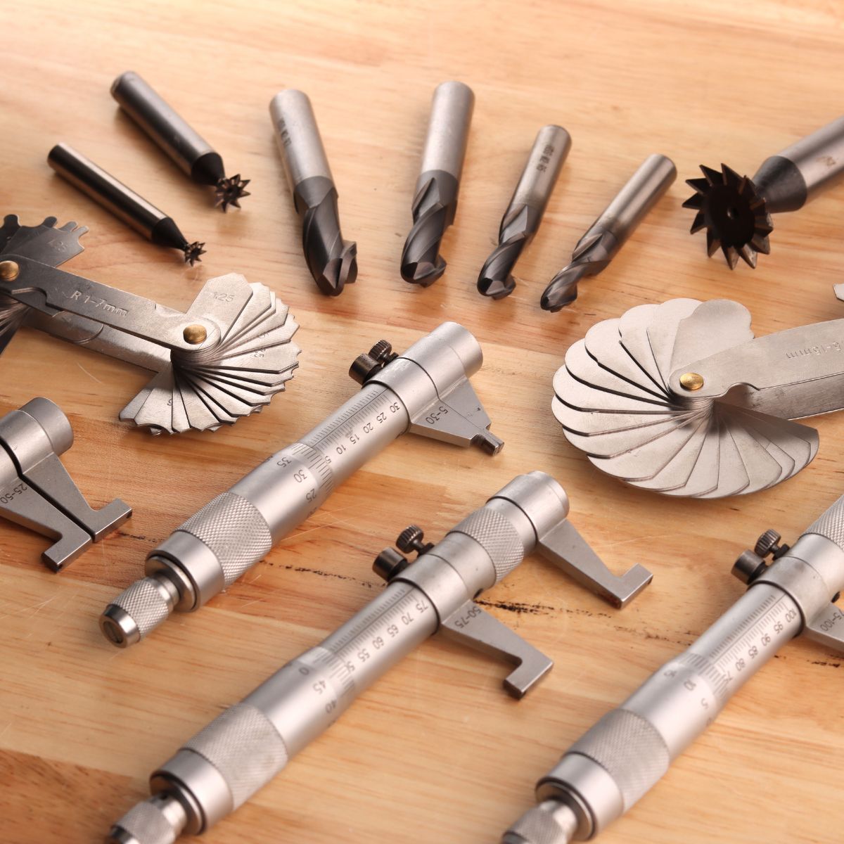
Lathe Tools and Equipment
General Purpose Cutting Tools
The lathe cutting tool or tool bit must be made of the correct material and ground to the correct angles to machine a workpiece efficiently. The most common tool bit is the general all-purpose bit made of high-speed steel. These tool bits are generally inexpensive, easy to grind on a bench or pedestal grinder, take lots of abuse and wear, and are strong enough for all-around repair and fabrication. High-speed steel tool bits can handle the high heat that is generated during cutting and are not changed after cooling. These tool bits are used for turning, facing, boring and other lathe operations. Tool bits made from special materials such as carbides, ceramics, diamonds, cast alloys are able to machine workpieces at very high speeds but are brittle and expensive for normal lathe work. High-speed steel tool bits are available in many shapes and sizes to accommodate any lathe operation.
Single Point Tool Bits
Single point tool bits can be one end of a high-speed steel tool bit or one edge of a carbide or ceramic cutting tool or insert. Basically, a single point cutter bit is a tool that has only one cutting action proceeding at a time. A machinist or machine operator should know the various terms applied to the single point tool bit to properly identify and grind different tool bits:
- The shank is the main body of the tool bit.
- The nose is the part of the tool bit which is shaped to a point and forms the corner between the side cutting edge and the end cutting edge. The nose radius is the rounded end of the tool bit.
- The face is the top surface of the tool bit upon which the chips slide as they separate from the workpiece.
- The side or flank of the tool bit is the surface just below and adjacent to the cutting edge.
- The cutting edge is the part of the tool bit that actually cuts into the workpiece, located behind the nose and adjacent to the side and face.
- The base is the bottom surface of the tool bit, which usually is ground flat during tool bit manufacturing.
- The end of the tool bit is the near-vertical surface which, with the side of the bit, forms the profile of the bit. The end is the trailing surface of the tool bit when cutting.
- The heel is the portion of the tool bit base immediately below and supporting the face.
Angles of Tool Bits
The performance of a lathe and the quality of the finished work depend greatly on the angles that form the cutting edge of the tool bit. Most tool bits are hand-ground on a bench or pedestal grinder to achieve the desired shape. Proper cutting geometry, including rake and relief angles, must be maintained to ensure smooth cutting and extended tool life. While the general shape of a tool bit may vary according to operator preference, what matters most is that the angles are correctly ground for the type of material being machined. Tool bits may have pointed, rounded, or squared profiles and still perform effectively when properly shaped. Key angles include side and back rake, side and end cutting edge angles, and side and end relief angles. Additional considerations include the nose radius and the tool holder angle. Once these relationships are understood, machinists can select the most suitable tool shapes for each cutting task.
Rake angle refers to the inclination of the tool’s top surface. It is divided into two main types: side rake and back rake. Depending on the cutting requirements, the rake angle may be positive, negative, or neutral. The tool holder itself also contributes to this geometry through the tool holder angle typically around 15° which, combined with the back rake angle, provides clearance for chip evacuation and prevents rubbing. The side rake angle, measured from the cutting edge, influences chip flow and cutting efficiency, and may be positive or neutral based on material hardness.
Excessive rake angles can weaken the cutting edge and cause chipping or tool failure. The side rake angle affects the type and direction of chips produced during cutting. To improve safety and chip control, a chip breaker may be integrated into the side rake to help fragment long, continuous chips into smaller, manageable pieces.
Side and relief angles—also called clearance angles are ground behind and below the cutting edge to prevent rubbing and allow the tool to cut freely. There are two types: side relief and end relief. The side relief is ground under the cutting edge to provide clearance along the direction of tool travel, while the end relief prevents the heel of the tool from contacting the workpiece. Together with the tool holder angle, these angles determine the effective clearance at the cutting point.
Side and cutting edge angles are formed between the cutting edge and the tool’s end or side surfaces. The end cutting edge angle allows the tool’s nose to contact the workpiece and assists with feed movement, while the side cutting edge angle reduces cutting pressure and improves surface finish. The combination of the side rake and side relief forms the wedge, or lip angle, which governs the cutting efficiency and strength of the edge.
A small nose radius ground at the tip of the tool strengthens the cutting edge and provides smoother surface finishes by reducing tool marks during operation.
Shapes of Tool Bits
The overall form of a tool bit may be rounded, square, or another custom shape, as long as it includes the proper angles for cutting. Tool bits are commonly identified by their intended function such as turning, facing, roughing, or finishing. A roughing tool typically has a smaller nose radius than a finishing tool, allowing it to remove material quickly, while finishing tools use larger radii for smoother surfaces. Experienced machinists often choose specific tool shapes based on the machining task and material type.
A right-hand turning tool bit is designed to cut when fed from right to left. Its cutting edge is on the left side, and the top face slopes downward away from that edge. The left and front faces are ground to provide sufficient clearance, ensuring that only the cutting edge contacts the workpiece. This tool is well suited for general-purpose cutting and light roughing operations.
A left-hand turning tool bit is the mirror opposite of the right-hand type and cuts when fed from left to right. It is primarily used when machining close to a right-hand shoulder or when access on the right-hand side is restricted.
The round-nose turning tool bit is one of the most versatile designs and can cut in either direction. It is suitable for both roughing and finishing operations. When used for bidirectional cutting, it typically has no side rake, although a slight back rake may be added to improve chip removal. The nose is ground into a half-circle, usually about 1/32 inch in radius, to promote smooth cutting and reduce tool wear.
The right-hand facing tool bit is intended for facing on right-hand side shoulders and the right end of a workpiece. The cutting edge is on the left-hand side of the bit, and the nose is ground very sharp for machining into a square corner. The direction of feed for this tool bit should be away from the centre axis of the work, not going into the centre axis.
A left-hand facing tool bit is the opposite of the right-hand facing tool bit and is intended to machine and face the left sides of shoulders.
The parting tool bit is also known as the cutoff tool bit. This tool bit has the principal cutting edge at the squared end of the bit that is advanced at a right angle into the workpiece. Both sides should have sufficient clearance to prevent binding and should be ground slightly narrower at the back than at the cutting edge. Besides being used for parting operations, this tool bit can be used to machine square corners and grooves.
Thread-cutting tool bits are ground to cut the type and style of threads desired. Side and front clearances must be ground, plus the special point shape for the type of thread desired. Thread-cutting tool bits can be ground for standard 60° thread forms or for square, Acme, or special threads.
Special Types of Lathe Cutting Tools
Besides the common shaped tool bits, special lathe operations and heavy production work require special types of cutting tools. Some of the more common of these tools are listed below.
Tungsten carbide, tantalum carbide, titanium carbide, ceramic, oxide, and diamond-tipped tool bits and cutting tool inserts are commonly used in high-speed production work when heavy cuts are necessary and where exceptionally hard and tough materials are encountered. Standard shapes for tipped tool bits are similar to high-speed steel-cutting tool shapes. Carbide and ceramic inserts can be square, triangular, round, or other shapes. The inserts are designed to be indexed or rotated as each cutting edge gets dull and then discarded. Cutting tool inserts are not intended for reuse after sharpening.
Specially formed thread cutter mounted in a thread cutter holder. This tool is designed for production high-speed thread cutting operations. The special design of the cutter allows for sharp and strong cutting edges which need only to be resharpened occasionally by grinding the face. The cutter mounts into a special tool holder that mounts to the lathe tool post.
The common knurling tool consists of two cylindrical cutters, called knurls, which rotate in a specially designed tool holder. The knurls contain teeth which are rolled against the surface of the workpiece to form depressed patterns on the workpiece. The common knurling tool accepts different pairs of knurls, each having a different pattern or pitch. The diamond pattern is most widely used and comes in three pitches: 14, 21, or 33. These pitches produce coarse, medium, and fine knurled patterns.
Boring tool bits are ground similar to left-hand turning tool bits and thread-cutting tool bits, but with more end clearance angle to prevent the heel of the tool bit from rubbing against the surface of the bored hole. The boring tool bit is usually clamped to a boring tool holder, but it can be a one-piece unit. The boring tool bit and tool holder clamp into the lathe tool post.
Grinding Tool Bits
While there is no single method for grinding lathe tool bits, several best practices should be followed to ensure both safety and precision. Never use a bench or pedestal grinder without first understanding its operation, safety precautions, and limitations. For effective grinding, the wheel must have a clean, true surface and be made of the correct abrasive material for the tool bit being shaped. Carbide tool bits should always be ground using a silicon carbide wheel, as standard wheels are not capable of cutting such hard material.
High-speed steel (HSS) tool bits are the only type suitable for grinding on a standard bench or pedestal grinder equipped with an aluminium oxide wheel the most common setup in maintenance and workshop environments. Before grinding, verify that the grinder is in safe working order and properly configured. Adjust tool rests, spark guards, and wheel covers as needed to provide a safe and stable setup.
Position the tool rest within 1/8 inch of the grinding wheel and the spark arrestor within 1/4 inch. Most grinders are equipped with a coarse wheel for shaping and a fine wheel for sharpening and finishing. Dress both wheels regularly to maintain a smooth and flat grinding surface. When forming side and back rake angles, use a wheel with a sharp corner for accurate shaping. To prevent overheating, dip the tool bit in water frequently while grinding this helps preserve the tool’s hardness and prevents burns. Continuously check the tool geometry with a protractor or dedicated grinding gauge to ensure correct angles. Once the final shape is achieved, lightly hone the tool on an oilstone to remove burrs and small imperfections. A polished tool edge results in a smoother surface finish on the workpiece.
Lathe Tool Holders and Tool Posts
Quick-Change Tool Posts & Holders


Tool holders are essential components that secure the cutting tool at the correct height and angle for precise machining. They attach to the lathe’s tool post, which provides the main support for a variety of tool holder types. Standard high-speed steel (HSS) tool holders are typically used with the round tool post supplied on most engine lathes. This assembly usually consists of a post, screw, washer, collar, and rocker that fit into the compound rest’s T-slot.
HSS tool holders feature a square slot that accommodates common tool bit sizes such as 1/4", 5/16", and 3/8". Different configurations exist to suit specific applications, including straight, right-hand, and left-hand offset holders, as well as zero-rake types for carbide inserts. Other compatible holders for standard tool posts include parting, knurling, boring bar, and thread-cutting types, each designed for a distinct machining task.
The turret tool post offers a rotating head capable of holding multiple tools simultaneously. This design allows operators to switch between tools quickly, making it ideal for high-volume or repetitive turning operations.
The heavy-duty or open-sided tool post is intended for single-tool setups, providing excellent rigidity and support for deep or heavy cuts.
The quick-change tool post system uses a dovetail-style mechanism with interchangeable holders that can be swapped out in seconds using a release knob. This design significantly improves workflow efficiency in workshops that require frequent tool changes.
Work Holding Devices
Many different devices, such as chucks, collets, faceplates, drive plates, mandrels, and lathe centres, are used to hold and drive the work whilst it is being machined on a lathe. The size and type of work to be machined and the particular operation that needs to be done will determine which work holding device is best for any particular job. Another consideration is how much accuracy is needed for a job, since some work holding devices are more accurate than others.
Universal Scroll Chuck
The universal scroll chuck usually has three jaws which move in unison as an adjusting pinion is rotated. The advantage of the universal scroll chuck is its ease of operation in centring work for concentric turning. This chuck is not as accurate as the independent chuck, but when in good condition it will centre work within 0.002 to 0.003 inches of runout.
The jaws are moved simultaneously within the chuck by a scroll or spiral-threaded plate. The jaws are threaded to the scroll and move an equal distance inward or outward as the scroll is rotated by the adjusting pinion. Since the jaws are individually aligned on the scroll, the jaws cannot usually be reversed. Some manufacturers supply two sets of jaws, one for internal work and one for external work. Other manufacturers make the jaws in two pieces so the outside, or gripping surface may be reversed, which can be interchanged.
The universal scroll chuck can be used to hold and automatically centre round or hexagonal workpieces. Having only three jaws, the chuck cannot be used effectively to hold square, octagonal, or irregular shapes.
Independent Chuck
The independent chuck typically features four jaws that can be adjusted individually using screws located on the chuck face. Concentric guide circles are scribed on the face to assist with rough alignment of round workpieces. For precise centring, the workpiece should be rotated slowly by hand while checking with a dial indicator, and each jaw adjusted as needed until the required concentricity is achieved.
The jaws of an independent chuck can be reversed to grip workpieces either externally or internally, depending on the job. Because each jaw operates independently, this chuck can hold workpieces of various shapes—round, square, hexagonal, or irregular either concentrically or eccentrically. This makes it highly adaptable for complex or non-standard shapes.
Due to its versatility and fine adjustment capability, the independent chuck is preferred when machining irregular or precision-critical workpieces that require exact positioning.
Combination Chuck
The combination chuck merges the advantages of the independent and universal scroll chucks. Available in both three- and four-jaw configurations, it allows the operator to move all jaws simultaneously for automatic centring or adjust them individually using separate screws when needed for fine alignment.
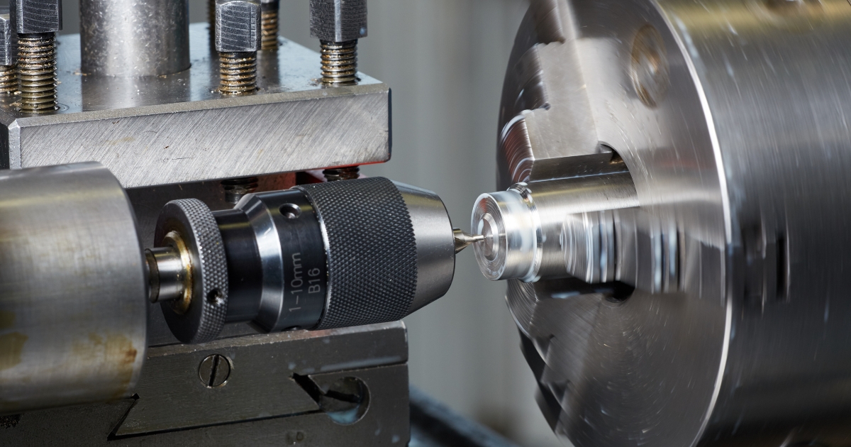
Drill Chuck
The drill chuck is a small, universal chuck commonly mounted in the headstock or tailstock spindle to hold straight-shank drills, reamers, taps, or small workpieces. It uses three or four hardened steel jaws that move together via a tapered sleeve mechanism. When properly tightened, a quality drill chuck can centre tools or small workpieces to within 0.002–0.003 inch accuracy.
Collet Chuck
The collet chuck provides the most accurate means of holding small workpieces on a lathe. It consists of a spring collet and a matching attachment that secures it to the headstock spindle. The spring collet is a thin, precision-machined metal sleeve with a tapered exterior and a bore that matches the workpiece diameter. Longitudinal slots allow the collet to flex slightly for a secure grip. For precision, the collet should be within 0.005 inch of the workpiece diameter. Standard collets are available in 1/64-inch increments and are typically limited to workpieces up to 1⅛ inches in diameter.
The collet attachment includes a collet sleeve, drawbar, and handwheel or lever that tightens the drawbar. As the drawbar is rotated, it pulls the collet into the tapered sleeve, compressing it around the workpiece. Spring collets come in various shapes round, square, and hexagonal to accommodate different workpiece profiles.
Jacob's Spindle-Nose Collet Chuck
The Jacob’s spindle-nose collet chuck is a compact, self-contained system designed for use with Jacob’s rubber-flex collets. It combines the functions of both a standard collet chuck and a drawbar. The outer housing features a handwheel used to tighten or release the internal tapered spindle that holds the rubber-flex collet. These collets, made of hardened steel jaws encased in rubber, can accommodate a range of 1/8 inch per collet while maintaining uniform grip and precision. They offer two to four times the holding strength of conventional split steel collets, making them ideal for heavy-duty turning applications. Sets of these collets are typically stored in dedicated steel cases for organisation and protection.
Step Chuck
The step chuck is a variation of the collet chuck designed for securing small round workpieces or discs that require special machining operations. Each step chuck is supplied as a blank and machined directly on the lathe to match the specific size of the workpiece. Like standard collets, step chucks are split into three sections and attach to the drawbar of a collet system for precise control.
Lathe Tailstock Chuck
The lathe tailstock chuck is used to support the end of a workpiece in the tailstock when a standard lathe centre cannot be conveniently applied. It features a tapered arbor that fits into the tailstock spindle and three self-centring bronze jaws that accurately grip workpieces from 1/4 to 1 inch in diameter. The bronze jaws provide excellent bearing surfaces and prevent damage to the material while maintaining accurate alignment during machining.
Lathe Faceplate
The lathe faceplate is a flat, circular plate that threads directly onto the headstock spindle. It is primarily used for securing irregularly shaped workpieces that cannot be held by a chuck or mounted between centres. Workpieces are attached to the faceplate using bolts, angle plates, or custom brackets. Radial T-slots in the plate allow flexible mounting configurations. The faceplate is especially useful for machining parts with off-centre holes or projections. A smaller version, known as a driving faceplate, is used with a lathe dog to drive workpieces held between centres. The driving faceplate usually has fewer T-slots and engages the lathe dog to transmit rotation from the spindle to the workpiece.
Lathe Centres
Lathe centres are the most common devices for supporting workpieces in the lathe. Most lathe centres have a tapered point with a 60° included angle to fit workpiece holes with the same angle. The workpiece is supported between two centres, one in the headstock spindle and one in the tailstock spindle. Centres for lathe work have standard tapered shanks that fit directly into the tailstock and into the headstock spindle using a centre sleeve to convert the larger bore of the spindle to the smaller tapered size of the lathe centre. The centres are referred to as live centres or dead centres. A live centre revolves with the work and does not need to be lubricated and hardened. A dead centre does not revolve with the work and must be hardened and heavily lubricated when holding work. Live and dead centres commonly come in matched sets, with the hardened dead centre marked with a groove near the conical end point.
The ball bearing live centre is a special centre mounted in a ball bearing housing that lets the centre turn with the work and eliminates the need for a heavily lubricated dead centre. Ball bearing types of centres can have interchangeable points which make this centre a versatile tool in all lathe operations. Modern centres of this type can be very accurate.
The male centre or plain centre is used in pairs for most general lathe turning operations. The point is ground to a 60° cone angle. When used in the headstock spindle where it revolves with the workpiece, it is commonly called a live centre. When used in the tailstock spindle where it remains stationary when the workpiece is turned, it is called a dead centre. Dead centres are always made of hardened steel and must be lubricated very often to prevent overheating.
The half male centre is a male centre that has a portion of the 60° cone cut away. The half male centre is used as a dead centre in the tailstock where facing is to be performed. The cutaway portion of the centre faces the cutting tool and provides the necessary clearance for the tool when facing the surface immediately around the drilled centre in the workpiece.
The V-centre is used to support round workpieces at right angles to the lathe axis for special operations such as drilling or reaming. The pipe centre is similar to the male centre but its cone is ground to a greater angle and is larger in size. It is used for holding pipe and tubing in the lathe.
The female centre is conically bored at the tip and is used to support workpieces that are pointed on the end. A self-driving lathe centre is a centre with serrated ground sides that can grip the work whilst turning between centres without having to use lathe dogs.
Lathe Dogs
Lathe dogs are cast metal devices used to provide a secure connection between the headstock spindle and a workpiece mounted between centres. This connection ensures the workpiece rotates at the same speed as the spindle during machining. There are three common types of lathe dogs, with variations that include bent tails and straight tails. Bent-tail dogs fit into a slot on the driving faceplate, while straight-tail dogs rest against a stud on the faceplate. The bent-tail lathe dog with a headless setscrew is considered safer than the version with a square-head screw, as it reduces the risk of catching on the operator’s clothing. For rectangular workpieces, a bent-tail clamp lathe dog is typically used.
Mandrels
When a workpiece cannot be held between centres due to a bored or drilled axis, and is unsuitable for mounting in a chuck or on a faceplate, it is often machined on a mandrel. A mandrel is a slightly tapered shaft pressed into the bore of the workpiece, allowing it to be supported accurately between centres.
A mandrel differs from an arbor, which is designed to hold cutting tools rather than workpieces. To avoid damaging the bore, lightly oil the mandrel before inserting it into the workpiece. When machining on a mandrel, always feed toward the large end, which should face the headstock for better stability.
A solid machine mandrel is typically made from hardened and ground steel, featuring a slight taper of about 0.0005 to 0.0006 inch per inch. Each end is accurately countersunk for mounting between centres, and machined flats on the smaller ends provide a secure grip for a lathe dog. The size of the mandrel is stamped on the large end of the taper. Because of their fixed taper, solid mandrels are limited to specific internal bore sizes.
An expansion mandrel accommodates a wider range of internal diameters. It functions like an expanding chuck, where adjustable segments are forced outward to grip the inside of the workpiece securely. Expansion mandrels are useful for holding slightly variable bore sizes or workpieces with light tolerance variations.
Lathe Attachments
The range of work a lathe can perform is greatly enhanced by using specialised attachments. Some machines include these accessories as standard equipment, while others are optional. Common lathe attachments include the steady rest (with or without a cathead), follower rest, tool post grinder, micrometer carriage stop, milling fixture, coolant system, indexing attachment, and multi-purpose milling-grinding-drilling-slotting units.
Steady Rest
The steady rest, or centre rest, supports long or slender workpieces during turning, boring, or internal threading operations, especially when the work extends a significant distance from the chuck or faceplate. The steady rest is clamped to the lathe bed and supports the work with three adjustable jaws. Before use, the area where the rest contacts the work should be machined to form a true bearing surface. The jaws must be adjusted precisely for alignment and lubricated frequently to minimise friction. The top section of the rest can swing open to allow removal of the workpiece without disturbing the jaw settings.
Cathead
When a workpiece is too small to provide a bearing surface for a steady rest, a cathead is used. A cathead has a central hole for the workpiece and several adjusting screws that allow it to be clamped securely. These screws are also used to align the cathead’s outer bearing surface concentrically with the workpiece axis. Proper setup requires a dial indicator to verify concentric alignment before machining begins.
Follower Rest
The follower rest is attached to the carriage and moves along with the cutting tool. It typically has one or two jaws that press against the workpiece just behind the cutting area, providing support and preventing deflection. The follower rest is ideal for straight turning or threading long, slender workpieces. To use it correctly, a short section of the work must first be turned before engaging the rest. Some steady and follower rests include ball-bearing jaws, which reduce friction and can operate without constant lubrication or a polished contact surface.
Micrometer Carriage Stop
The micrometer carriage stop enables precise positioning of the carriage for repetitive or critical machining operations. The carriage is moved against a retractable spindle on the stop and locked in place. The built-in micrometer scale allows for fine adjustments as small as 0.001 inch. This attachment is especially useful for facing operations, turning shoulders, or cutting grooves to exact lengths.
Tool Post Grinder
The tool post grinder is a machine tool attachment specially designed for cylindrical grinding operations on the lathe. It consists primarily of a 1/4-or 1/3-horsepower electric motor and a wheel spindle connected by pulleys and a belt. The machine fastens to the compound rest of the lathe with a T-slot bolt which fits in the slot of the compound rest in the same manner as the lathe tool post. The tool post grinding machine mounts grinding abrasive wheels ranging from 1/4 inch to 3 or 4 inches in diameter for internal and external grinding operations. The pulleys on the wheel spindle and motor shaft are interchangeable to provide proper cutting speeds for the various wheel sizes. The larger grinding abrasive wheels used for external grinding are attached to the wheel spindle with an arbor. Small, mounted grinding abrasive wheels for internal grinding are fixed in a chuck which screws to the wheel spindle. The electric motor is connected to an electrical power source by a cable and plug. A switch is usually provided at the attachment to facilitate starting and stopping the motor.
Lathe Milling Fixture
This is a fixture designed to provide the ability for limited milling operations. Many repair and fabrication jobs cannot be satisfactorily completed on the standard engine lathe, but with the lathe milling attachment, the small machine shop that is not equipped with a milling machine can mill keyslots, keyways, flats, angles, hex heads, squares, splines, and holes.
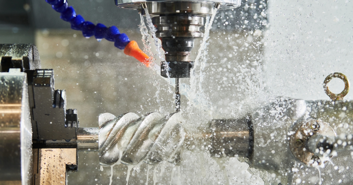
Cutting Fluids

Cutting fluids serve several important functions on a lathe: they cool both the cutting tool and the workpiece, extend tool life, improve surface finish, prevent rust, and help clear chips away from the cutting area. Depending on the machining process, cutting fluids can be applied by spraying, dripping, wiping, or flooding the cutting zone. In most cases, they are used when high cutting speeds or heavy loads generate excessive heat that could damage the tool or workpiece.
Lard Oil
Pure lard oil is one of the oldest and most effective traditional cutting oils. It provides excellent lubrication and is particularly useful for thread cutting, tapping, deep-hole drilling, and reaming operations. Lard oil offers strong adhesion, maintains its viscosity across a wide temperature range, and provides a natural rust-preventive quality while producing a smooth surface finish. Due to its high cost, it is typically blended with other ingredients to form more economical cutting oil mixtures with similar performance.
Mineral Oil
Mineral oils are petroleum-based and vary in viscosity from light kerosene to thicker paraffin oils. They are chemically stable and less prone to odour formation than lard oil but offer lower adhesion, lubricity, and heat absorption. Because they are inexpensive, mineral oils are often blended with lard oil or additives to improve cutting performance. In pure form, kerosene and turpentine are commonly used for machining aluminium and magnesium, while paraffin oil—alone or mixed with lard oil, is suitable for machining brass and copper.
Mineral-Lard Cutting Oil Mixture
Blending mineral oil with lard oil combines the best characteristics of both effective lubrication, cooling, and rust resistance—at a lower cost than pure lard oil. These mixtures are widely used for general-purpose cutting applications where a balanced performance is required.
Sulphurised Fatty-Mineral Oil
Modern high-performance cutting oils often contain mineral and lard oils enhanced with sulphur and chlorine additives. These elements provide strong anti-weld properties, reducing friction and preventing metal from fusing to the tool. Such oils are ideal for machining tough or high-tensile materials, offering excellent surface finishes and extended tool life.
Soluble Cutting Oils
Water has excellent cooling capability but lacks lubricating properties and promotes rust. To overcome this, soluble oils emulsions of mineral or lard oils mixed with water are used. The lubricating quality depends on the mixture’s strength. Soluble cutting oils are particularly effective in roughing operations where rapid heat dissipation is crucial. Additives like borax or trisodium phosphate (TSP) are sometimes included to enhance corrosion protection.
Soda-Water Mixtures
Soda-water coolants are made by dissolving salts such as soda ash or TSP in water to help prevent rust. This inexpensive mixture offers minimal lubrication but excellent cooling, making it suitable for reaming and threading cast iron where surface finish improvement is desired. Small amounts of lard oil or soap are sometimes added to increase lubricity.
White Lead and Lard Oil Mixture
Mixing white lead with lard or mineral oil produces a dense, high-pressure cutting lubricant ideal for machining very hard metals. It provides superior adhesion and helps reduce tool wear when working with difficult materials.
Laying Out and Mounting Work

Most lathe jobs require little or no layout work because the machine itself guides the cutting tool with high accuracy. However, when centre holes must be located and drilled into the ends of a workpiece and this cannot be done directly on the lathe, alternative marking methods are used. These include using a bell-type centre punch between centres, scribing intersecting arcs with hermaphrodite callipers, employing the centring head of a combination square, or using dividers to find the true centre before drilling.
Mounting Workpieces in Chucks
When installing a chuck or any spindle-mounted attachment, always ensure the threads and bearing surfaces of both the chuck and the spindle are clean and lightly oiled. A spring thread cleaner can be helpful for cleaning the internal chuck threads before installation.
Rotate the spindle until the keyway is facing upward, then lock the spindle securely in place. Verify that both the spindle nose and chuck taper are completely free of chips or debris. Position the chuck on the spindle and engage the draw nut thread. Tighten the draw nut by applying several firm hammer taps on the spanner wrench, then rotate the spindle 180° and repeat. This ensures even seating and prevents misalignment. Once secured, the chuck is ready for the workpiece to be mounted.
Workpieces automatically centre themselves in self-centring chucks such as the three-jaw universal chuck, drill chuck, collet chuck, or step chuck. In contrast, independent four-jaw chucks require manual centring. To centre work in an independent chuck, align the jaws roughly to the required diameter using the concentric guide rings on the chuck face. Place the workpiece in position, tighten the jaws lightly, and spin the workpiece by hand to make approximate centring adjustments. Once close, gradually tighten the jaws evenly to secure the piece.
For irregularly shaped workpieces, start by measuring the diameter and adjusting the jaws so the work fits loosely. Tighten each opposing jaw evenly until the work is held firmly but not excessively tight. To roughly identify the high side, hold a piece of chalk near the rotating workpiece where the chalk touches marks the high point. Loosen the jaw opposite and tighten the one at the mark, repeating until the work is nearly centred.
For smooth, round stock or high-precision setups, use a dial test indicator. Place the indicator’s tip against the outside or inside surface of the workpiece and rotate it slowly by hand, observing deviations on the dial. Adjust the jaws as needed until the runout is within acceptable tolerance, typically a few thousandths of an inch.
When aligning irregularly shaped workpieces, machinists often use a hardened steel bar with a 60° point held in the tailstock drill chuck. The bar is guided into the centre-punched mark on the workpiece, and a dial indicator is used to fine-tune alignment to within 0.001 inch. If a hardened bar is unavailable, a hardened centre in the tailstock can serve the same purpose. Over time, experience will guide operators toward the most efficient alignment methods for different shapes and setups.
Mounting Work to Faceplates
Faceplates are mounted onto the spindle in the same manner as chucks. After installation, check the faceplate’s surface with a dial indicator and, if necessary, take a light truing cut to restore accuracy. Avoid using the same faceplate on multiple lathes, as repeated truing cuts will eventually cause excessive wear. When securing workpieces, use correctly sized T-bolts and clamps, ensuring all contact surfaces are free of chips, burrs, and dirt. If a heavy workpiece is mounted off-centre such as with an angle plate use a counterweight to balance the load and minimise vibration. Insert thin brass or paper shims between the work and the faceplate to prevent surface damage. After roughly positioning the work, use a dial indicator to fine-tune the alignment for precision machining.
Mounting Work Between Centres
Before mounting a workpiece between centres, the workpiece ends must be centre-drilled and countersunk. This can be done using a small twist drill followed by a 60° centre countersink or, more commonly, using a countersink and drill (also commonly called a centre drill). It is very important that the centre holes are drilled and countersunk so that they will fit the lathe centres exactly. Incorrectly drilled holes will subject the lathe centres to unnecessary wear and the workpiece will not run true because of poor bearing surfaces. A correctly drilled and countersunk hole has a uniform 60° taper and has clearance at the bottom for the point of the lathe centre. The holes should have a polished appearance so as not to score the lathe centres. The actual drilling and countersinking of centre holes can be done on a drilling machine or on the lathe itself. Before attempting to centre drill using the lathe, the end of the workpiece must be machined flat to keep the centre drill from running off centre.
Mount the work in a universal or independent chuck and mount the centre drill in the lathe tailstock. Centre drills come in various sizes for different diameters of work. Calculate the correct speed and hand feed into the workpiece. Only drill into the workpiece about 2/3 of the body diameter. Use high speeds and feed them into the work slowly to avoid breaking off the drill point inside the work. If this happens, the work must be removed from the chuck and the point extracted. This is a time-consuming job and could ruin the workpiece.
To mount work between centres, the operator must know how to insert and remove lathe centres. The quality of workmanship depends as much on the condition of the lathe centres as on the proper drilling of the centre holes. Before mounting lathe centres in the headstock or tailstock, thoroughly clean the centres, the centre sleeve, and the tapered sockets in the headstock and tailstock spindles. Any dirt or chips on the centres or in their sockets will prevent the centres from seating properly and will cause the centres to run out of true.
Install the lathe centre in the tailstock spindle with a light twisting motion to ensure a clean fit. Install the centre sleeve into the headstock spindle and install the lathe centre into the centre sleeve with a light twisting motion.
To remove the centre from the headstock spindle, hold the pointed end securely with a cloth or rag and give it a sharp tap using a knockout bar or rod inserted through the hollow spindle. To remove the centre from the tailstock, turn the handwheel to retract the spindle until the centre makes contact with the internal screw, which will release it from its socket.
After mounting both the headstock and tailstock centres, check the accuracy of the 60° point with a centre gauge or dial indicator. If the headstock centre is worn, burred, or not a true 60°, it must be re-trued while mounted in the spindle. A soft centre (not hardened) can be trued with a cutting tool, while a hardened centre requires grinding using a tool post grinder for precision results.
To true a soft centre, set up the tool bit for right-hand turning and align it on centre. Rotate the compound rest to 30° relative to the lathe’s axis. Use a fine feed rate and finishing speed, advancing the tool via the compound handwheel to create a short, accurate 60° taper. Once trued, leave the centre in position throughout the machining operation. If it must be removed, mark both the centre and spindle for realignment later.
Lathe centres must be perfectly parallel to the bed ways to ensure that turned parts remain straight and accurate. Before starting any turning operation, verify centre alignment. The tailstock can be moved laterally for fine adjustment using the alignment screws once it has been released from the bed. Two reference lines at the rear of the tailstock assist with rough alignment. Bring the tailstock close to the headstock and compare the two centres visually to confirm they are nearly touching and properly aligned.
The most accurate way to check centre alignment is to mount a workpiece between centres and take a light trial cut at both ends without adjusting the carriage. Measure both diameters with a micrometer or callipers. If the tailstock end is larger, move the tailstock slightly toward the operator. If it is smaller, move it away. Repeat the process, taking light cuts after each adjustment, until both ends measure the same diameter.
When setting up a workpiece between centres, use a driving faceplate (or drive plate) and a lathe dog. Ensure that the external spindle threads are clean before screwing on the faceplate, and secure it firmly. Clamp the lathe dog to the workpiece so its tail overhangs the end. If the surface is finished, place a thin brass shim under the setscrew to prevent damage. Mount the work between centres and confirm that the dog tail fits freely into the faceplate slot. If the tailstock centre is a dead centre (non-rotating), apply a few drops of oil mixed with white lead for lubrication. Adjust the tailstock so the centre fits snugly in the workpiece’s centre hole without binding. During machining, stop the lathe periodically to reapply lubricant to prevent overheating and wear.
Mounting Work on Mandrels
When machining components with internal bores such as pulleys or gears a tapered mandrel provides accurate support between centres. Mount the mandrel between centres and drive it with a faceplate and lathe dog. Ensure that both centres are clean, aligned, and free of burrs. Press the lubricated mandrel into the workpiece bore using an arbor press to achieve a firm, concentric fit. Secure the lathe dog to the machined flat at the end of the mandrel, not the smooth tapered section. If expansion bushings are used, clean and maintain them as you would a standard mandrel. Always feed the cutting tool toward the larger end of the mandrel (towards the headstock) to prevent the workpiece from loosening. When facing work on a mandrel, take care not to cut into the mandrel surface itself.
General Lathe Operations

Lathe Speeds, Feeds, and Depth of Cuts
Common lathe operations include straight and shoulder turning, facing, grooving, parting, taper turning, and thread cutting. Each process depends on the correct combination of spindle speed, feed rate, and depth of cut. Understanding these variables is essential to prevent tool wear, machine strain, and poor surface finishes. The optimal settings depend on several factors: the material being machined, the type and geometry of the tool bit, the size and rigidity of the workpiece, the nature of the operation (roughing or finishing), and the condition of the lathe itself. Selecting the right speed and feed ensures efficient cutting, extended tool life, and high-quality results.
Cutting Speeds
The cutting speed of a tool bit is defined as the number of feet of workpiece surface, measured at the circumference, that passes the tool bit in one minute. The cutting speed, expressed in FPM, must not be confused with the spindle speed of the lathe which is expressed in RPM. To obtain uniform cutting speed, the lathe spindle must be revolved faster for workpieces of small diameter and slower for workpieces of large diameter. The proper cutting speed for a given job depends upon the hardness of the material being machined, the material of the tool bit, and how much feed and depth of cut is required. Cutting speeds for metal are usually expressed in surface feet per minute, measured on the circumference of the work. Spindle revolutions per minute (RPM) are determined by using the formula:
Which is simplified to:
RPM = (SFM × 4) / D
Where:
SFM is the rated surface feet per minute, also expressed as cutting speed
RPM is the spindle speed in revolutions per minute
D is the diameter of the work in inches
In order to use the formula simply insert the cutting speed of the metal and the diameter of the workpiece into the formula and you will have the RPM. For example, turning a one-half inch piece of aluminium, cutting speed of 200 SFM, would result in the following:
Hard materials require a slower cutting speed than soft or ductile materials. Materials that are machined dry, without coolant, require a slower cutting speed than operations using coolant. Lathes that are worn and in poor condition will require slower speeds than machines that are in good shape. If carbide-tipped tool bits are being used, speeds can be increased two to three times the speed used for high-speed tool bits.
Feed
Feed is the term applied to the distance the tool bit advances along the work for each revolution of the lathe spindle. Feed is measured in inches or millimetres per revolution, depending on the lathe used and the operator's system of measurement. A light feed must be used on slender and small workpieces to avoid damage. If an irregular finish or chatter marks develop whilst turning, reduce the feed and check the tool bit for alignment and sharpness. Regardless of how the work is held in the lathe, the tool should feed towards the headstock. This results in most of the pressure of the cut being put on the work holding device. If the cut must be fed towards the tailstock, use light feeds and light cuts to avoid pulling the workpiece loose.
Depth of Cut
The depth of cut refers to how far the cutting tool penetrates into the workpiece surface, typically measured in thousandths of an inch or millimetres. As a general rule, the depth of cut is set up to five times the feed rate. For example, when rough cutting stainless steel with a feed of 0.020 inch per revolution, a depth of cut of 0.100 inch will remove a total of 0.200 inch from the workpiece diameter. If chatter or excessive noise occurs during machining, reduce the depth of cut to restore stability.
Micrometer Collar
Micrometer collars are used to measure the precise movement of the tool bit toward or away from the lathe’s centre axis. The cross slide and compound rest are both equipped with these graduated collars, allowing accurate measurement of the tool’s travel. Depending on the design, some collars measure actual tool movement, while others display the total reduction in workpiece diameter (double the tool movement). They are available with inch, metric, or dual readouts. Always consult the machine’s operator manual for specific information about collar calibration and measurement conventions.
Facing
Facing is the operation of machining the end of a workpiece to make it smooth, flat, and perpendicular to the spindle axis. It is used to bring the workpiece to an exact length and to produce a clean surface suitable for measurement or subsequent machining.
Facing Work in a Chuck
Facing is commonly performed with the work held in a chuck or collet. The workpiece should not project more than 1½ times its diameter beyond the chuck jaws. Set spindle speed and feed according to the largest workpiece diameter. The tool may be fed either from the outer edge toward the centre or from the centre outward. Facing from the outer edge inward is most common, as it allows better visibility of the cutting area and prevents tool binding in the solid centre. Use a left-hand finishing tool bit with a right-hand tool holder for this method. When facing from the centre outward such as when the part has a central bore, use a right-hand finishing tool bit. Minimise tool overhang to reduce vibration and ensure the cutting edge is set exactly on the centreline to prevent leaving a small nub in the middle. If no tailstock centre is available for alignment, make a light trial cut and adjust accordingly. When using power feed, disengage it about 1/16 inch from the centre and complete the cut manually for better control.
Facing Work Between Centres
When a workpiece is too large or irregular to be held in a chuck or collet, facing between centres is required. Before mounting, ensure the workpiece has centre-drilled holes. Use a half male centre in the tailstock, lubricated with an oil and white lead mixture, to provide clearance for the cutting tool. The tool bit must have a sharp point to cut up to the edge of the centre hole. Begin the facing cut at the inner edge of the centre hole and feed outward. Use light, finishing feeds to minimise pressure on the half male centre. Once facing is complete, replace the half male centre with a standard centre, as it provides better support for turning operations. Avoid removing too much material, as it may weaken the centre holes and reduce work support.
Precision Facing
When parts must be faced to an exact length, precision techniques are required. One approach is to lightly face one end of the workpiece, then reverse it in the chuck and face to the layout line for length. While adequate for general work, higher precision can be achieved by setting the compound rest at a 30° angle to the cross slide and using the micrometer collar to control tool movement. At this angle, the tool advances half the amount indicated on the collar, so a 0.010-inch collar movement removes 0.005 inch of material. Lock the carriage to the bed during facing to provide a solid base and reduce vibration. Another method is to use a micrometer carriage stop to measure and control carriage travel, offering fast and repeatable length control, especially for production operations.
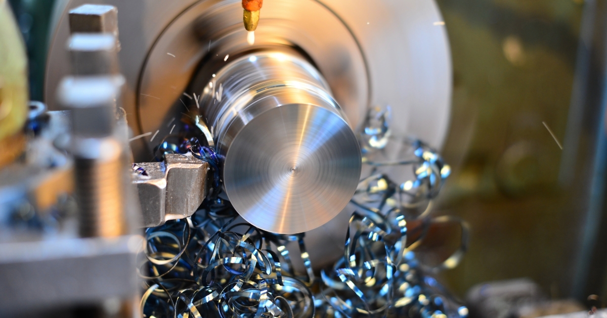
Straight Turning
Straight turning, also known as cylindrical turning, involves reducing the diameter of a rotating workpiece along its entire length to achieve a uniform dimension. The tool moves parallel to the spindle axis, maintaining a consistent cut. The process generally includes a roughing pass followed by a finishing pass. When removing large amounts of material, multiple roughing cuts may be required. Roughing cuts should be as deep as the tool and machine can handle, while the finishing pass should be light and accurate to achieve the final specified size in one pass. When using power feed for turning to length, d
Setting Depth of Cut
In straight turning, the cross feed or compound rest graduated collars are used to determine the depth of cut, which will remove a desired amount from the workpiece diameter. When using the graduated collars for measurement, make all readings when rotating the handles in the forward direction. The lost motion in the gears, called backlash, prevents taking accurate readings when the feed is reversed. If the feed screw must be reversed, such as to restart a cut, then the backlash must be taken up by turning the feed screw handle in the opposite direction until the movement of the screw actuates the movement of the cross slide or compound rest. Then turn the feed screw handle in the original or desired direction back to the required setting.
Setting Tool Bit for Straight Turning
For most straight turning operations, the compound rest should be aligned at an angle perpendicular to the cross slide, and then swung 30° to the right and clamped in position. The tool post should be set on the left-hand side of the compound rest T-slot, with a minimum of tool bit and tool holder overhang.
When the compound rest and tool post are in these positions, the danger of running the cutting tool into the chuck or damaging the cross slide are minimised. Position the roughing tool bit about 5° above centre height for the best cutting action. This is approximately 3/64-inch above centre for each inch of the workpiece diameter. The finishing tool bit should be positioned at centre height since there is less torque during finishing. The position of the tool bit to the work should be set so that if anything occurs during the cutting process to change the tool bit alignment, the tool bit will not dig into the work, but instead will move away from the work. Also, by setting the tool bit in this position, chatter will be reduced. Use a right-hand turning tool bit with a slight round radius on the nose for straight turning. Always feed the tool bit towards the headstock unless turning up to an inside shoulder. Different workpieces can be mounted in a chuck, in a collet, or between centres. Which work holding device to use will depend on the size of the work and the particular operation that needs to be performed.
Turning Work Between Centres
Turning between centres is one of the most accurate machining methods for cylindrical parts. Its main advantage is that the workpiece can be removed and later remounted without losing alignment, ensuring that all turned surfaces remain concentric to the original centre holes. For precise results, ensure both lathe centres are clean, in good condition, and correctly aligned. If necessary, true or regrind the centres before use. After centre-drilling the workpiece, attach a lathe dog slightly larger than the work diameter to the headstock end and tighten it securely. When using a dead centre in the tailstock, lubricate it with a mixture of white lead and oil. A ball-bearing live centre is preferred because it eliminates the need for lubrication and reduces friction. Extend the tailstock spindle approximately 3 inches and secure the tailstock once the centre supports the work. Check that the lathe dog tail fits freely into the drive-plate slot, allowing clearance at both the top and bottom. Apply enough tension to keep the work steady but not so tight that it restricts movement.
Before starting, move the cutting tool to its furthest safe position to confirm it clears the lathe dog and drive plate. Set a carriage or micrometer stop at this point to prevent overtravel and protect the lathe components. Select appropriate speed, feed, and depth of cut for the material and perform a rough cut to within approximately 0.020 inch of the final size. Then take a light finishing pass. For complete symmetry, reverse the workpiece, move the lathe dog to the opposite end, and repeat the roughing and finishing operations to bring both ends to final dimensions.
Turning Work in Chucks
Many turning operations are performed using chucks, collets, mandrels, or faceplates to hold the work securely. The cutting techniques for roughing and finishing are generally the same as when turning between centres. Ensure the workpiece does not extend excessively beyond the holding device without proper support. If the overhang exceeds three times the diameter of the workpiece, use a steady rest or tailstock support to prevent deflection and chatter. When machining irregular or unbalanced parts mounted on a mandrel or faceplate, take light cuts and feed the tool toward the headstock to maintain control. Every job may require a unique setup depending on the workpiece shape, weight, and desired accuracy. Over time, experience will guide machinists in selecting the most effective setup for each situation.
Machining Shoulders, Corners, Undercuts, Grooves, and Parting
Shoulders
Many turned parts include sections of different diameters. The transition point between these sections is known as a shoulder. Shoulders can serve several purposes: they strengthen parts where components fit together, provide precise locating surfaces, or improve the appearance of a component. The workpiece can be mounted in a chuck, collet, mandrel, or between centres for shoulder machining. The most common types of shoulders are square, filleted, and angular.
Square shoulders are suitable for parts not exposed to high stress at the corners. They provide flat, square surfaces for accurate assembly. One method to cut a square shoulder is to use a parting tool to mark and cut the shoulder depth, then reduce the diameter by straight turning. Another method is to rough the shoulder slightly oversize with a round-nose tool, then finish to size usi
Undercuts
Undercuts are the reductions in diameter machined onto the centre portion of workpieces to lighten the piece or to reduce an area of the part for special reasons, such as holding an oil seal ring. Some tools, such as drills and reamers, require a reduction in diameter at the ends of the flutes to provide clearance or runout for a milling cutter or grinding wheel. Reducing the diameter of a shaft or workpiece at the centre with filleted shoulders at each end may be accomplished by the use of a round-nosed turning tool bit. This tool bit may or may not have a side rake angle, depending on how much machining needs to be done. A tool bit without any side rake is best when machining in either direction. Undercutting is done by feeding the tool bit into the workpiece whilst moving the carriage back and forth slightly. This prevents gouging and chatter occurring on the work surface.
Grooves
Grooving (or necking) is the process of turning a groove or furrow on a cylinder, shaft, or workpiece. The shape of the tool and the depth to which it is fed into the work govern the shape and size of the groove. The types of grooves most commonly used are square, round, and V-shaped. Square and round grooves are frequently cut on work to provide a space for tool runout during subsequent machining operations, such as threading or knurling. These grooves also provide a clearance for assembly of different parts. The V-shaped groove is used extensively on step pulleys made to fit a V-type belt. The grooving tool is a type of forming tool. It is ground without side or back rake angles and set to the work at centre height with a minimum of overhang. The side and end relief angles are generally somewhat less than for turning tools.
In order to cut a round groove of a definite radius on a cylindrical surface, the tool bit must be ground to fit the proper radius gauge. Small V-grooves may be machined by using a form tool ground to size or just slightly undersize. Large V-grooves may be machined with the compound rest by finishing each side separately at the desired angle. This method reduces tool bit and work contact area, thus reducing chatter, gouging, and tearing. Since the cutting surface of the tool bit is generally broad, the cutting speed must be slower than that used for general turning. A good guide is to use half of the speed recommended for normal turning. The depth of the groove, or the diameter of the undercut, may be checked by using outside callipers or by using two wires and an outside micrometer.
When a micrometer and two wires are used, the micrometer reading is equal to the measured diameter of the groove plus two wire diameters. To calculate measurement over the wires, use the following formula:
Parting
Parting is the process of cutting off a piece of stock whilst it is being held in the lathe. This process uses a specially shaped tool bit with a cutting edge similar to that of a square-nosed tool bit. When parting, be sure to use plenty of coolant, such as a sulphurised cutting oil (machine cast iron dry). Parting tools normally have a 5° side rake and no back rake angles. The blades are sharpened by grinding the ends only. Parting is used to cut off stock, such as tubing, that is impractical to saw off with a power hacksaw.
Parting is also used to cut off work after other machining operations have been completed. Parting tools can be of the forged type, inserted blade type, or ground from a standard tool blank. In order for the tool to have maximum strength, the length of the cutting portion of the blade should extend only enough to be slightly longer than half of the workpiece diameter (able to reach the centre of the work). Never attempt to part whilst the work is mounted between centres.
Work that is to be parted should be held rigidly in a chuck or collet, with the area to be parted as close to the holding device as possible. Always make the parting cut at a right angle to the centreline of the work. Feed the tool bit into the revolving work with the cross slide until the tool completely severs the work. Speeds for parting should be about half that used for straight turning. Feeds should be light but continuous. If chatter occurs, decrease the feed and speed, and check for loose lathe parts or a loose setup. The parting tool should be positioned at centre height unless cutting a piece that is over 1-inch thick. Thick pieces should have the cutting tool just slightly above centre to account for the stronger torque involved in parting. The length of the portion to be cut off can be measured by using the micrometer carriage stop or by using layout lines scribed on the workpiece. Always have the carriage locked down to the bed to reduce vibration and chatter.
Radii and Form Turning
Occasionally, a radius or irregular shape must be machined on the lathe. Form turning is the process of machining radii and these irregular shapes. The method used to form-turn will depend on the size and shape of the object, the accuracy desired, the time allowed, and the number of pieces that need to be formed. Of the several ways to form-turn, using a form turning tool that is ground to the shape of the desired radius is the most common. Other common methods are using hand manipulation and filing, using a template and following rod, or using the compound rest and tool to pivot and cut. Two radii are cut in form turning, concave and convex. A concave radius curves inward and a convex radius curves outward.
Forming a Radius Using a Form Turning Tool
Using a form turning tool to cut a radius is a way to form small radii and contours that will fit the shape of the tool. Forming tools can be ground to any desired shape or contour, with the only requirements being that the proper relief and rake angles must be ground into the tool's shape. The most practical use of the ground forming tool is in machining several duplicate pieces, since the machining of one or two pieces will not warrant the time spent on grinding the form tool. Use the proper radius gauge to check for correct fit. A forming tool has a lot of contact with the work surface, which can result in vibration and chatter. Slow the speed, increase the feed, and tighten the work setup if these problems occur.
Forming a Radius Using Hand Manipulation
Hand manipulation, or free hand, is the most difficult method of form turning to master. The cutting tool moves on an irregular path as the carriage and cross slide are simultaneously manipulated by hand. The desired form is achieved by watching the tool as it cuts and making small adjustments in the movement of the carriage and cross slide. Normally, the right hand works the cross feed movement whilst the left hand works the carriage movement. The accuracy of the radius depends on the skill of the operator. After the approximate radius is formed, the workpiece is filed and polished to a finished dimension.
Forming a Radius Using a Template
To use a template with a follower rod to form a radius, a full scale form of the work is laid out and cut from thin sheet metal. This form is then attached to the cross slide in such a way that the cutting tool will follow the template. The accuracy of the template will determine the accuracy of the workpiece. Each lathe model has a cross slide and carriage that are slightly different from one another, but they all operate in basically the same way. A mounting bracket must be fabricated to hold the template to allow the cutting tool to follow its shape. This mounting bracket can be utilised for several different operations, but should be sturdy enough for holding clamps and templates. The mounting bracket must be positioned on the carriage to allow for a follower (that is attached to the cross slide) to contact the template and guide the cutting tool. For this operation, the cross slide must be disconnected from the cross feed screw and hand pressure applied to hold the cross slide against the follower and template. Rough-cut the form to the approximate shape before disconnecting the cross feed screw. This way, a finish cut is all that is required whilst applying hand pressure to the cross slide. Some filing may be needed to completely finish the work to dimension.
Forming a Radius Using the Compound Rest
To use the compound rest and tool to pivot and cut, the compound rest bolts must be loosened to allow the compound rest to swivel. When using this method, the compound rest and tool are swung from side to side in an arc. The desired radius is formed by feeding the tool in or out with the compound slide. The pivot point is the centre swivel point of the compound rest. A concave radius can be turned by positioning the tool in front of the pivot point, whilst a convex radius can be turned by placing the tool behind the pivot point. Use the micrometer carriage stop to measure precision depths of different radii.
[Content continues with extensive sections on Taper Turning, Screw Thread Cutting, and Special Operations...]
Taper Turning
When the diameter of a piece changes uniformly from one end to the other, the piece is said to be tapered. Taper turning as a machining operation is the gradual reduction in diameter from one part of a cylindrical workpiece to another part. Tapers can be either external or internal. If a workpiece is tapered on the outside, it has an external taper; if it is tapered on the inside, it has an internal taper. There are three basic methods of turning tapers with a lathe. Depending on the degree, length, location of the taper (internal or external), and the number of pieces to be done, the operator will either use the compound rest, offset the tailstock, or use the taper attachment. With any of these methods the cutting edge of the tool bit must be set exactly on centre with the axis of the workpiece or the work will not be truly conical and the rate of taper will vary with each cut.
Compound Rests
The compound rest is favourable for turning or boring short, steep tapers, but it can also be used for longer, gradual tapers providing the length of taper does not exceed the distance the compound rest will move upon its slide. This method can be used with a high degree of accuracy, but is somewhat limited due to lack of automatic feed and the length of taper being restricted to the movement of the slide.
The compound rest base is graduated in degrees and can be set at the required angle for taper turning or boring. With this method, it is necessary to know the included angle of the taper to be machined. The angle of the taper with the centreline is one-half the included angle and will be the angle the compound rest is set for. For example, to true up a lathe centre which has an included angle of 60°, the compound rest would be set at 30° from parallel to the ways.
If there is no degree of angle given for a particular job, then calculate the compound rest setting by finding the taper per inch, and then calculating the tangent of the angle (which is the compound rest setting).
angle = compound rest setting
Where:
TPI = taper per inch
D = large diameter
d = small diameter
L = length of taper
The problem is actually worked out by substituting numerical values for the letter variables. Apply the formula to find the angle by substituting the numerical values for the letter variables. Using trig charts, the angle can be found. The included angle of the workpiece is double that of the tangent of angle (compound rest setting).
To machine a taper by this method, the tool bit is set on centre with the workpiece axis. Turn the compound rest feed handle in a counterclockwise direction to move the compound rest near its rear limit of travel to assure sufficient traverse to complete the taper. Bring the tool bit into position with the workpiece by traversing and cross-feeding the carriage. Lock the carriage to the lathe bed when the tool bit is in position. Cut from right to left, adjusting the depth of cut by moving the cross feed handle and reading the calibrated collar located on the cross feed handle. Feed the tool bit by hand-turning the compound rest feed handle in a clockwise direction.
Offsetting the Tailstock
The oldest and probably most used method of taper turning is the offset tailstock method. The tailstock is made in two pieces: the lower piece is fitted to the bed, whilst the upper part can be adjusted laterally to a given offset by use of adjusting screws and lineup marks. Since the workpiece is mounted between centres, this method of taper turning can only be used for external tapers. The length of the taper is from headstock centre to tailstock centre, which allows for longer tapers than can be machined using the compound rest or taper attachment methods.
The tool bit travels along a line which is parallel with the ways of the lathe. When the lathe centres are aligned and the workpiece is machined between these centres, the diameter will remain constant from one end of the piece to the other. If the tailstock is offset, the centreline of the workpiece is no longer parallel with the ways; however, the tool bit continues its parallel movement with the ways, resulting in a tapered workpiece. The tailstock may be offset either towards or away from the operator. When the offset is towards the operator, the small end of the workpiece will be at the tailstock with the diameter increasing towards the headstock end.
The offset tailstock method is applicable only to comparatively gradual tapers because the lathe centres, being out of alignment, do not have full bearing on the workpiece. Centre holes are likely to wear out of their true positions if the lathe centres are offset too far, causing poor results and possible damage to centres.
The most difficult operation in taper turning by the offset tailstock method is determining the proper distance the tailstock should be moved over to obtain a given taper. Two factors affect the amount the tailstock is offset: the taper desired and the length of the workpiece. If the offset remains constant, workpieces of different lengths, or with different depth centre holes, will be machined with different tapers.
The formula for calculating the tailstock offset when the taper is given in taper inches per foot (tpf) is as follows:
Where:
Offset = tailstock offset (in inches)
TPF = taper (in inches per foot)
L = length of taper (in feet) measured along the axis of the workpiece
The formula for calculating the tailstock offset when the taper is given in TPI is as follows:
Where:
OFFSET = tailstock offset
TPI = taper per inch
L = length of taper in inches
If the workpiece has a short taper in any part of its length and the TPI or TPF is not given, use the following formula:
Where:
D = Diameter of large end
d = Diameter of small end
L = Total length of workpiece in inches
L1 = Length of taper
Metric tapers can also be calculated for taper turning by using the offset tailstock method. Metric tapers are expressed as a ratio of 1 mm per unit of length. If the small diameter (d), the unit length of taper (k), and the total length of taper (l) are known, then the large diameter (D) may be calculated. The large diameter (D) will be equal to the small diameter plus the amount of taper.
Where:
D = large diameter
d = small diameter
l = length of taper
L = length of the workpiece
Another important consideration in calculating offset is the distance the lathe centres enter the workpiece. The length of the workpiece (L) should be considered as the distance between the points of the centres for all offset computations. Therefore, if the centres enter the workpiece 1/8 inch on each end and the length of the workpiece is 18 inches, subtract 1/4 inch from 18 inches and compute the tailstock offset using 17 3/4 inches as the workpiece length (L).
The amount of taper to be cut will govern the distance the top of the tailstock is offset from the centreline of the lathe. The tailstock is adjusted by loosening the clamp nuts, shifting the upper half of the tailstock with the adjusting screws, and then tightening them in place.
There are several methods the operator may use to measure the distance the tailstock has been offset depending upon the accuracy desired. One method is to gauge the distance the lineup marks on the rear of the tailstock have moved out of alignment. This can be done by using a 6-inch rule placed near the lineup marks or by transferring the distance between the marks to the rule's surface using a pair of dividers. Another common method uses a rule to check the amount of offset when the tailstock is brought close to the headstock.
Where accuracy is required, the amount of offset may be measured by means of the graduated collar on the cross feed screw. First compute the amount of offset; next, set the tool holder in the tool post so the butt end of the holder faces the tailstock spindle. Using the cross feed, run the tool holder in by hand until the butt end touches the tailstock spindle. The pressure should be just enough to hold a slip of paper placed between the tool holder and the spindle. Next, move the cross slide to bring the tool holder towards you to remove the backlash. The reading on the cross feed micrometer collar may be recorded, or the graduated collar on the cross feed screw may be set at zero. Using either the recorded reading or the zero setting for a starting point, bring the cross slide towards you the distance computed by the offset. Loosen and offset the tailstock until the slip of paper drags when pulled between the tool holder and the spindle. Clamp the tailstock to the lathe bed.
Another and possibly the most precise method of measuring the offset is to use a dial indicator. The indicator is set on the centre of the tailstock spindle whilst the centres are still aligned. A slight loading of the indicator is advised since the first 0.010 or 0.020 inches of movement of the indicator may be inaccurate due to mechanism wear causing fluctuating readings. Load the dial indicator as follows: Set the bezel to zero and move tailstock towards the operator the calculated amount. Then clamp the tailstock to the way.
Whichever method is used to offset the tailstock, the offset must still be checked before starting to cut. Set the dial indicator in the tool post with its spindle just barely touching far right side of the workpiece. Then, rotate the carriage towards the headstock exactly 1 inch and take the reading from the dial indicator. One inch is easily accomplished using the thread chasing dial. It is 1 inch from one number to another. Alternatively, 1 inch can be drawn out on the workpiece. The dial indicator will indicate the taper for that 1 inch and, if needed, the tailstock can be adjusted as needed to the precise taper desired. If this method of checking the taper is not used, then an extensive trial and error method is necessary.
To cut the taper, start the rough turning at the end which will be the small diameter and feed longitudinally towards the large end. The tailstock is offset towards the operator and the feed will be from right to left. The tool bit, a right-hand turning tool bit or a round-nose turning tool bit, will have its cutting edge set exactly on the horizontal centreline of the workpiece, not above centre as with straight turning.
Taper Attachment
The taper attachment has many features of special value, among which are the following:
- The lathe centres remain in alignment and the centre holes in the work are not distorted.
- The alignment of the lathe need not be disturbed, thus saving considerable time and effort.
- Taper boring can be accomplished as easily as taper turning.
- A much wider range is possible than by the offset method. For example, to machine a 3/4-inch-per-foot taper on the end of a bar 4 feet long would require an offset of 1 1/2 inches, which is beyond the capabilities of a regular lathe but can be accomplished by use of the taper attachment.
Some engine lathes are equipped with a taper attachment as standard equipment and most lathe manufacturers have a taper attachment available. Taper turning with a taper attachment, although generally limited to a taper of 3 inches per foot and to a set length of 12 to 24 inches, affords the most accurate means for turning or boring tapers. The taper can be set directly on the taper attachment in inches per foot; on some attachments, the taper can be set in degrees as well.
Ordinarily, when the lathe centres are in line, the work is turned straight, because as the carriage feeds along, the tool is always the same distance from the centreline. The purpose of the taper attachment is to make it possible to keep the lathe centres in line, but by freeing the cross slide and then guiding it (and the tool bit) gradually away from the centreline, a taper can be cut or, by guiding it gradually nearer the centreline, a taper hole can be bored.
A plain taper attachment for the lathe consists of a bed bracket that attaches to the lathe bed and keeps the angle plate from moving to the left or the right. The carriage bracket moves along the underside of the angle plate in a dovetail and keeps the angle plate from moving in or out on the bed bracket. The taper to be cut is set by placing the guide bar, which clamps to the angle plate, at an angle to the ways of the lathe bed. Graduations on one or both ends of the guide bar are used to make this adjustment. A sliding block which rides on a dovetail on the upper surface of the guide bar is secured during the machining operation to the cross slide bar of the carriage, with the cross feed screw of the carriage being disconnected. Therefore, as the carriage is traversed during the feeding operation, the cross slide bar follows the guide bar, moving at the predetermined angle from the ways of the bed to cut the taper. It is not necessary to remove the taper attachment when straight turning is desired. The guide bar can be set parallel to the ways, or the clamp handle can be released permitting the sliding block to move without affecting the cross slide bar, and the cross feed screw can be re-engaged to permit power cross feed and control of the cross slide from the apron of the carriage.
Modern lathes often use a telescopic taper attachment. This attachment allows for using the cross feed, and set up is a bit faster than using a standard taper attachment. To use the telescopic attachment, first set the tool bit for the required diameter of the work and engage the attachment by tightening the binding screws, the location and number of which depend upon the design of the attachment. The purpose of the binding screws is to bind the cross slide so it may be moved only by turning the cross feed handle, or, when loosened, to free the cross slide for use with the taper attachment. To change back to straight turning with the telescopic attachment, it is necessary only to loosen the binding screws.
When cutting a taper using the taper attachment, the direction of feed should be from the intended small diameter towards the intended large diameter. Cutting in this manner, the depth of cut will decrease as the tool bit passes along the workpiece surface and will assist the operator in preventing possible damage to the tool bit, workpiece, and lathe by forcing too deep a cut.
The length of the taper the guide bar will allow is usually not over 12 to 24 inches, depending on the size of the lathe. It is possible to machine a taper longer than the guide bar allows by moving the attachment after a portion of the desired taper length has been machined; then the remainder of the taper can be cut. However, this operation requires experience.
If a plain standard taper attachment is being used, remove the binding screw in the cross slide and set the compound rest perpendicular to the ways. Use the compound rest graduated collar for depth adjustments.
When using the taper attachment, there may be a certain amount of "lost motion" (backlash) which must be eliminated or serious problems will result. In every slide and every freely revolving screw there is a certain amount of lost motion which is very noticeable if the parts are worn. Care must be taken to remove lost motion before proceeding to cut or the workpiece will be turned or bored straight for a short distance before the taper attachment begins to work. To take up lost motion when turning tapers, run the carriage back towards the dead centre as far as possible, then feed forward by hand to the end of the workpiece where the power feed is engaged to finish the cut. This procedure must be repeated for every cut.
The best way to bore a taper with a lathe is to use the taper attachment. Backlash must be removed when tapers are being bored with the taper attachment, otherwise the hole will be bored straight for a distance before the taper starts. Two important factors to consider: the boring tool must be set exactly on centre with the workpiece axis, and it must be small enough in size to pass through the hole without rubbing at the small diameter. A violation of either of these factors will result in a poorly formed, inaccurate taper or damage to the tool and workpiece. The clearance of the cutter bit shank and boring tool bar must be determined for the smaller diameter of the taper. Taper boring is accomplished in the same manner as taper turning.
To set up the lathe attachment for turning a taper, the proper TPF must be calculated and the taper attachment set-over must be checked with a dial indicator prior to cutting. Calculate the taper per foot by using the formula:
Where:
TPF = taper per foot
D = large diameter (in inches)
d = small diameter (in inches)
L = length of taper
After the TPF is determined, the approximate angle can be set on the graduated TPF scale of the taper attachment. Use a dial indicator and a test bar to set up for the exact taper. Check the taper in the same manner as cutting the taper by allowing for backlash and moving the dial indicator along the test bar from the tailstock end to the headstock end. Check the TPI by using the thread-chasing dial, or using layout lines of 1-inch size, and multiply by 12 to check the TPF. Make any adjustments needed, set up the work to be tapered, and take a trial cut. After checking the trial cut and making final adjustments, continue to cut the taper to required dimensions as in straight turning. Some lathes are set up in metric measurement instead of inch measurement. The taper attachment has a scale graduated in degrees, and the guide bar can be set over for the angle of the desired taper. If the angle of the taper is not given, use the following formula to determine the amount of the guide bar set over:
Where:
D = large diameter of taper (mm)
d = small diameter of taper (mm)
l = length of taper (mm)
L = length of guide bar (mm)
Reference lines must be marked on the guide bar an equal distance from the centre for best results. A metric dial indicator can be used to measure the guide bar set over, or the values can be changed to inch values and an inch dial indicator used.
Checking Tapers for Accuracy
Tapers must be checked for uniformity after cutting a trial cut. Lay a good straight edge along the length of the taper and look for any deviation of the angle or surface. Deviation is caused by backlash or a lathe with loose or worn parts. A bored taper may be checked with a plug gauge by marking the gauge with chalk or Prussian blue pigment. Insert the gauge into the taper and turn it one revolution. If the marking on the gauge has been rubbed evenly, the angle of taper is correct. The angle of taper must be increased when there is not enough contact at the small end of the plug gauge, and it must be decreased when there is not enough contact at the large end of the gauge. After the correct taper has been obtained but the gauge does not enter the workpiece far enough, additional cuts must be taken to increase the diameter of the bore.
An external taper may be checked with a ring gauge. This is achieved by the same method as for checking internal tapers, except that the workpiece will be marked with the chalk or Prussian blue pigment rather than the gauge. Also, the angle of taper must be decreased when there is not enough contact at the small end of the ring gauge and it must be increased when there is not enough contact at the large end of the gauge. If no gauge is available, the workpiece should be tested in the hole it is to fit. When even contact has been obtained, but the tapered portion does not enter the gauge or hole far enough, the diameter of the piece is too large and must be decreased by additional depth of cut.
Another good method of checking external tapers is to scribe lines on the workpiece 1 inch apart; then, take measurements with an outside micrometer. Subtracting the small reading from the large reading will give the taper per inch.
Duplicating a Tapered Piece
When the taper on a piece of work is to be duplicated and the original piece is available, it may be placed between centres on the lathe and checked with a dial indicator mounted in the tool post. When the setting is correct, the dial indicator reading will remain constant when moved along the length of taper.
This same method can be used on workpieces without centres provided one end of the workpiece can be mounted and held securely on centre in the headstock of the lathe. For example, a lathe centre could be mounted in the lathe spindle by use of the spindle sleeve, or a partially tapered workpiece could be held by the non-tapered portion mounted in a collet or a chuck. Using either of these two methods of holding the work, the operator could use only the compound rest or the taper attachment for determining and machining the tapers.
Standard Tapers
There are various standard tapers in commercial use, the most common ones being the Morse tapers, the Brown and Sharpe tapers, the American Standard Machine tapers, the Jarno tapers, and the Standard taper pins.
Morse tapers are used on a variety of tool shanks, and exclusively on the shanks of twist drills. The taper for different numbers of Morse tapers is slightly different, but is approximately 5/8 inch per foot in most cases.
Brown and Sharpe tapers are used for taper shanks on tools such as end mills and reamers. The taper is approximately 1/2 inch per foot for all sizes except for taper No 10, where the taper is 0.5161 inch per foot.
The American Standard machine tapers are composed of a self-holding series and a steep taper series. The self-holding taper series consists of 22 sizes. The name "self-holding" has been applied where the angle of the taper is only 2° or 3° and the shank of the tool is so firmly seated in its socket that there is considerable frictional resistance to any force tending to turn or rotate the tool in the holder. The self-holding tapers are composed of selected tapers from the Morse, the Brown and Sharpe, and the 3/4-inch-per foot machine taper series. The smaller sizes of self-holding tapered shanks are provided with a tang to drive the cutting tool. Larger sizes employ a tang drive with the shank held by a key, or a key drive with the shank held with a draw bolt. The steep machine tapers consist of a preferred series and an intermediate series. A steep taper is defined as a taper having an angle large enough to ensure the easy or self-releasing feature. Steep tapers have a 3 1/2-inch taper per foot and are used mainly for aligning milling machine arbors and spindles, and on some lathe spindles and their accessories.
The Jarno taper is based on such simple formulas that practically no calculations are required when the number of taper is known. The taper per foot of all Jarno tapers is 0.600 inch per foot. The diameter at the large end is as many eighths, the diameter at the small end is as many tenths, and the length as many half-inches as indicated by the number of the taper. For example: A No 7 Jarno taper is 7/8 inch in diameter at the large end; 7/10 or 0.7 inch in diameter at the small end; and 7/2, or 3 1/2 inches long. The Jarno taper is used on various machine tools, especially profiling machines and die-sinking machines. It has also been used for the headstock and tailstock spindles on some lathes.
The Standard taper pins are used for positioning and holding parts together and have a 1/4-inch taper per foot. Standard sizes in these pins range from No 7/0 to No 10. The tapered holes used in conjunction with the tapered pins utilise the processes of step-drilling and taper reaming.
To preserve the accuracy and efficiency of tapers (shanks and holes), they must be kept free from dirt, chips, nicks, or burrs. The most important thing in regard to tapers is to keep them clean. The next most important thing is to remove all oil by wiping the tapered surfaces with a soft, dry cloth before use, because an oily taper will not hold.
Screw Thread Cutting on a Lathe
Screw threads are cut with the lathe for accuracy and for versatility. Both inch and metric screw threads can be cut using the lathe. A thread is a uniform helical groove cut inside of a cylindrical workpiece, or on the outside of a tube or shaft. Cutting threads by using the lathe requires a thorough knowledge of the different principles of threads and procedures of cutting. Hand coordination, lathe mechanisms, and cutting tool angles are all interrelated during the thread cutting process. Before attempting to cut threads on the lathe a machine operator must have a thorough knowledge of the principles, terminology and uses of threads.
Screw Thread Terminology
The common terms and definitions below are used in screw thread work and will be used in discussing threads and thread cutting:
- External or male thread is a thread on the outside of a cylinder or cone.
- Internal or female thread is a thread on the inside of a hollow cylinder or bore.
- Pitch is the distance from a given point on one thread to a similar point on a thread next to it, measured parallel to the axis of the cylinder. The pitch in inches is equal to one divided by the number of threads per inch.
- Lead is the distance a screw thread advances axially in one complete revolution. On a single-thread screw, the lead is equal to the pitch. On a double-thread screw, the lead is equal to twice the pitch, and on a triple-thread screw, the lead is equal to three times the pitch.
- Crest (also called "flat") is the top or outer surface of the thread joining the two sides.
- Root is the bottom or inner surface joining the sides of two adjacent threads.
- Side is the surface which connects the crest and the root (also called the flank).
- Angle of the thread is the angle formed by the intersection of the two sides of the threaded groove.
- Depth is the distance between the crest and root of a thread, measured perpendicular to the axis.
- Major diameter is the largest diameter of a screw thread.
- Minor diameter is the smallest diameter of a screw thread.
- Pitch diameter is the diameter of an imaginary cylinder formed where the width of the groove is equal to one-half of the pitch. This is the critical dimension of threading as the fit of the thread is determined by the pitch diameter (Not used for metric threads).
- Threads per inch is the number of threads per inch may be counted by placing a rule against the threaded parts and counting the number of pitches in 1 inch. A second method is to use the screw pitch gauge. This method is especially suitable for checking the finer pitches of screw threads.
- A single thread is a thread made by cutting one single groove around a rod or inside a hole. Most hardware made, such as nuts and bolts, has single threads. Double threads have two grooves cut around the cylinder. There can be two, three, or four threads cut around the outside or inside of a cylinder. These types of special threads are sometimes called multiple threads.
- A right-hand thread is a thread in which the bolt or nut must be turned to the right (clockwise) to tighten.
- A left hand thread is a thread in which the bolt or nut must turn to the left (counterclockwise) to tighten.
- Thread fit is the way a bolt and nut fit together as to being too loose or too tight.
- Metric threads are threads that are measured in metric measurement instead of inch measurement.
Screw Thread Forms
The most commonly used screw thread forms are detailed in the following paragraphs. One of the major problems in industry is the lack of a standard form for fastening devices. The screw thread forms that follow attempt to solve this problem; however, there is still more than one standard form being used in each industrial nation. The International Organisation for Standardisation (ISO) met in 1975 and drew up a standard metric measurement for screw threads, the new ISO Metric thread Standard (previously known as the Optimum Metric Fastener System). Other thread forms are still in general use today, including the American (National) screw thread form, the square thread, the Acme thread, the Brown and Sharpe 29° worm screw thread, the British Standard Whitworth thread, the Unified thread, and different pipe threads. All of these threads can be cut by using the lathe.
- The ISO Metric thread standard is a simple thread system that has threaded sizes ranging in diameter from 1.6 mm to 100 mm. These metric threads are identified by the capital M, the nominal diameter, and the pitch. For example, a metric thread with an outside diameter of 5 mm and a pitch of 0.8 mm would be given as M 5 x 0.8. The ISO metric thread standard simplifies thread design, provides for good strong threads, and requires a smaller inventory of screw fasteners than used by other thread forms. This ISO Metric thread has a 60° included angle and a crest that is 1.25 times the pitch (which is similar to the National thread form). The depth of thread is 0.6134 times the pitch, and the flat on the root of the thread is wider than the crest. The root of the ISO Metric thread is 0.250 times the pitch.
- The American (National) screw thread form is divided into four series, the National Coarse (NC), National Fine (NF), National Special (NS), and National Pipe threads (NPT). All series of this thread form have the same shape and proportions. This thread has a 60° included angle. The root and crest are 0.125 times the pitch. This thread form is widely used in industrial applications for fabrication and easy assembly and construction of machine parts.
- The British Standard Whitworth thread form thread has a 55° thread form in the V-shape. It has rounded crests and roots.
- The Unified thread form is now used instead of the American (National) thread form. It was designed for interchangeability between manufacturing units in the United States, Canada, and Great Britain. This thread is a combination of the American (National) screw thread form and the British Whitworth screw thread forms. The thread has a 60° angle with a rounded root, whilst the crest can be rounded or flat. (In the United States, a flat crest is preferred.) The internal thread of the unified form is like the American (National) thread form but is not cut as deep, leaving a crest of one-fourth the pitch instead of one-eighth the pitch. The coarse thread series of the unified system is designated UNC, whilst the fine thread series is designated UNF.
- The American National 29° Acme was designed to replace the standard square thread, which is difficult to machine using normal taps and machine dies. This thread is a power transmitting type of thread for use in jacks, vises, and feed screws.
- The Brown and Sharpe 29° worm screw thread uses a 29° angle, similar to the Acme thread. The depth is greater and the widths of the crest and root are different. This is a special thread used to mesh with worm gears and to transmit motion between two shafts at right angles to each other that are on separate planes. This thread has a self-locking feature making it useful for winches and steering mechanisms.
- The square screw thread is a power transmitting thread that is being replaced by the Acme thread. Some vises and lead screws may still be equipped with square threads. Contact areas between the threads are small, causing screws to resist wedging, and friction between the parts is minimal.
- The spark plug thread (international metric thread type) is a special thread used extensively in Europe, but seen only on some spark plugs in the United States. It has an included angle of 60° with a crest and root that are 0.125 times the depth.
- Different types of pipe thread forms are in use that have generally the same characteristics but different fits.
Thread Fit and Classifications
The Unified and American (National) thread forms designate classifications for fit to ensure that mated threaded parts fit to the tolerances specified. The unified screw thread form specifies several classes of threads which are Classes 1A, 2A, and 3A for screws or external threaded parts, and 1B, 2B, and 3B for nuts or internal threaded parts. Classes 1A and 1B are for a loose fit where quick assembly and rapid production are important and shake or play is not objectionable. Classes 2A and 2B provide a small amount of play to prevent galling and seizure in assembly and use, and sufficient clearance for some plating. Classes 2A and 2B are recommended for standard practice in making commercial screws, bolts, and nuts. Classes 3A and 3B have no allowance and 75 percent of the tolerance of Classes 2A and 2B. A screw and nut in this class may vary from a fit having no play to one with a small amount of play. Only high grade products are held to Class 3 specifications.
Four distinct classes of screw thread fits between mating threads (as between bolt and nut) have been designated for the American (National) screw thread form. Fit is defined as "the relation between two mating parts with reference to ease of assembly." These four fits are produced by the application of tolerances which are listed in the standards.
The four fits are described as follows:
- Class 1 fit is recommended only for screw thread work where clearance between mating parts is essential for rapid assembly and where shake or play is not objectionable.
- Class 2 fit represents a high quality of thread product and is recommended for the great bulk of interchangeable screw thread work.
- Class 3 fit represents an exceptionally high quality of commercially threaded product and is recommended only in cases where the high cost of precision tools and continual checking are warranted.
- Class 4 fit is intended to meet very unusual requirements more exacting than those for which Class 3 is intended. It is a selective fit if initial assembly by hand is required. It is not, as yet, adaptable to quantity production.
Thread Designations
In general, screw thread designations give the screw number (or diameter) first, then the thread per inch. Next is the thread series containing the initial letter of the series, NC (National Coarse), UNF (Unified Fine), NS (National Special), and so forth, followed by the class of fit. If a thread is left-hand, the letters LH follow the fit. An example of designations is as follows:
Two samples and explanations of thread designations are as follows:
- No 12 (0.216) - 24 NC-3. This is a number 12 (0.216-inch diameter) thread, 24 National Coarse threads per inch, and Class 3 fit.
- 1/4-28 UNF-2A LH. This is a 1/4-inch diameter thread, 28 Unified Fine threads per inch, Class 2A fit, and left-hand thread.
Metric Thread Fit and Tolerance
The older metric screw thread system has over one hundred different thread sizes and several ways of designating the fit between parts, including tolerance grades, tolerance positions, and tolerance classes. A simpler system was devised with the latest ISO Metric thread standard that uses one internal fit and two external fit designations to designate the tolerance (class) of fit. The symbol 6H is used to designate the fit for an internal thread (only the one symbol is used). The two symbols 6g and 5g6g are used to designate the fit for an external thread, 6g being used for general purpose threads and 5g6g used to designate a close fit. A fit between a pair of threaded parts is indicated by the internal thread (nut) tolerance fit designation followed by the external thread (bolt) tolerance fit designation with the two separated by a stroke. An example is M 5 x 0.8-5g6g/6H, where the nominal or major diameter is 5 mm, the pitch is 0.8 mm, and a close fit is intended for the bolt and nut.
Thread Cutting Tool Bits
Cutting V-threads with a 60 degrees thread angle is the most common thread cutting operation done on a lathe. V-threads, with the 60 degree angle, are used for metric thread cutting and for American (National) threads and Unified threads. To properly cut V-shaped threads, the single point tool bit must be ground for the exact shape of the thread form, to include the root of the thread.
For metric and American (National) thread forms, a flat should be ground at the point of the tool bit, perpendicular to the centre line of the 60° thread angle. For unified thread forms, the tip of the tool bit should be ground with a radius formed to fit the size of the root of the thread. Internal unified threads have a flat on the tip of the tool bit. In all threads listed above, the tool bit should be ground with enough side relief angle and enough front clearance angle.
For Acme and 29° worm screw threads, the cutter bit must be ground to form a point angle of 29°. Side clearances must be sufficient to prevent rubbing on threads of steep pitch. The end of the bit is then ground to a flat which agrees with the width of the root for the specific pitch being cut. Thread-cutting tool gauges are available to simplify the procedure and make computations unnecessary.
To cut square threads, a special thread-cutter bit is required. Before the square thread-cutter bit can be ground, it is necessary to compute the helix angle of the thread to be cut. The tool bit should be ground to the helix angle. The clearance angles for the sides should be within the helix angle. Note that the sides are also ground in towards the shank to provide additional clearance. The end of the tool should be ground flat, the flat being equal to one-half the pitch of the thread to produce equal flats and spaces on the threaded part.
When positioning the thread-cutter bit for use, place it exactly on line horizontally with the axis of the workpiece. This is especially important for thread-cutter bits since a slight variation in the vertical position of the bit will change the thread angle being cut.
The thread-cutter bit must be positioned so that the centreline of the thread angle ground on the bit is exactly perpendicular to the axis of the workpiece. The easiest way to make this alignment is by use of a centre gauge. The centre gauge will permit checking the point angle at the same time as the alignment is being effected. The centre gauge is placed against the workpiece and the cutter bit is adjusted on the tool post so that its point fits snugly in the 60° angle notch of the centre gauge.
Thread Cutting Operations
In cutting threads on a lathe, the pitch of the thread or number of threads per inch obtained is determined by the speed ratio of the headstock spindle and the lead screw which drives the carriage. Lathes equipped for thread cutting have gear arrangements for varying the speed of the lead screw. Modern lathes have a quick-change gearbox for varying the lead screw to spindle ratio so that the operator need only follow the instructions on the direction plates of the lathe to set the proper feed to produce the desired number of threads per inch. Once set to a specific number of threads per inch, the spindle speed can be varied depending upon the material being cut and the size of the workpiece without affecting the threads per inch.
The carriage is connected to the lead screw of the lathe for threading operations by engaging the half nut on the carriage apron with the lead screw. A control is available to reverse the direction of the lead screw for left or right-hand threading as desired. Be sure the lead screw turns in the proper direction. Feed the cutter bit from right to left to produce a right-hand thread. Feed the cutter bit from left to right to produce a left-hand thread.
For cutting standard 60° right-hand threads of the sharp V-type, such as the metric form, the American (National) form, and the Unified form, the tool bit should be moved in at an angle of 29° to the right. (Set the angle at 29° to the left for left-hand threads). Cutting threads with the compound rest at this angle allows for the left side of the tool bit to do most of the cutting, thus relieving some strain and producing a free curling chip. The direction is controlled by setting the compound rest at the 29° angle before adjusting the cutter bit perpendicular to the workpiece axis. The depth of cut is then controlled by the compound rest feed handle.
For Acme and 29° worm threads, the compound rest is set at one-half of the included angle (14 1/2°) and is fed in with the compound rest. For square threads, the cutter bit is fed into the workpiece at an angle perpendicular to the workpiece axis.
Before cutting threads, turn down the workpiece to the major diameter of the thread to be cut and chamfer the end. The workpiece may be set up in a chuck, in a collet, or between centres. If a long thread is to be cut, a steady rest or other support must be used to help decrease the chance of bending the workpiece. Lathe speed is set for the recommended threading speed. To cut threads, move the threading tool bit into contact with the work and zero the compound rest dial. The threading tool bit must be set at the right end of the work; then, move the tool bit in the first depth of cut by using the graduated collar of the compound rest. Position the carriage half nut lever to engage the half nut to the lead screw in order to start the threading operation. The first cut should be a scratch cut of no more than 0.003 inch so the pitch can be checked. Engaging the half nut with the lead screw causes the carriage to move as the lead screw revolves. Cut the thread by making a series of cuts in which the threading tool follows the original groove for each cut. Use the thread chasing dial to determine when to engage the half nut so that the threading tool will track properly. The dial is attached to the carriage and is driven by means of the lead screw. Follow the directions of the thread chasing dial to determine when to engage the half nut lever.
After making the first pass check for proper pitch of threads. If the thread pitch is correct as set in the quick-change gearbox, continue to cut the thread to the required depth. This is determined by measuring the pitch diameter and checking the reference table for the proper pitch diameter limits for the desired fit. Some lathes are equipped with a thread chasing stop bolted to the carriage which can be set to regulate the depth of cut for each traverse of the cutter bit or can be set to regulate the total depth of cut of the thread.
When the thread is cut the end must be finished in some way. The most common means of finishing the end is with a specially ground or 45 degree angle chamfer cutting bit. To produce a rounded end, a cutter bit with the desired shape should be specially ground for that purpose.
Metric Thread Cutting Operations
Metric threads are cut one of two ways by using the lathe, designed and equipped for metric measurement or by using a standard inch lathe and converting its operation to cut metric threads. A metric measurement lathe has a quick-change gear box used to set the proper screw pitch in millimetres. An inch-designed lathe must be converted to cut metric threads by switching gears in the lathe headstock according to the directions supplied with each lathe.
Most lathes come equipped with a set of changeable gears for cutting different, or nonstandard screw threads. Follow the directions in the lathe operator manual for setting the proper metric pitch. (A metric data plate may be attached to the lathe headstock.) Most lathes have the capability of quickly attaching these change gears over the existing gears then realigning the gearing. One change gear is needed for the lead screw gear and one for the spindle, or drive gear.
The metric thread diameter and pitch can be easily measured with a metric measuring tool. If there are no metric measuring tools available, the pitch and diameter must be converted from millimetres to inch measurement, and then an inch micrometer and measuring tools can be used to determine the proper pitch and diameter. Millimetres may be converted to inch measurement either by dividing millimetres by 25.4 inches or multiplying by 0.03937 inches.
For example, a thread with a designation M20 x 2.5 6g/6h is read as follows: the M designates the thread is metric. The 20 designates the major diameter in millimetres. The 2.5 designates the linear pitch in millimetres. The 6g/6h designates that a general purpose fit between nut and bolt is intended. Therefore, to machine this metric thread on an inch designed lathe, convert the outside diameter in millimetres to a decimal fraction of an inch and machine the major diameter to the desired diameter measurement. Convert the linear pitch in millimetres, to threads per inch by dividing the linear pitch of 2.5 by 25.4 to get the threads per inch (10.16 TPI). Now an 8-13 TPI thread micrometer can be used to measure the pitch diameter for this metric thread.
To sum up how to convert metric threads to inch measurement:
- Convert major diameter from millimetres to inch measure.
- Convert pitch and pitch diameter to inch measure.
- Set quick change gears according to instructions.
Set up the lathe for thread cutting as in the preceding paragraphs on screw thread cutting. Take a light trial cut and check that the threads are of the correct pitch using a metric screw pitch gauge. At the end of this trial cut, and any cut when metric threading, turn off the lathe and back out the tool bit from the workpiece without disengaging the half-nut-lever. Never disengage the lever until the metric thread is cut to the proper pitch diameter, or the tool bit will have to be realigned and set for chasing into the thread.
After backing the tool bit out from the workpiece, traverse the tool bit back to the starting point by reversing the lathe spindle direction whilst leaving the half-nut lever engaged. If the correct pitch is being cut, continue to machine the thread to the desired depth.
Tapered Screw Threads
Tapered screw threads or pipe threads can be cut on the lathe by setting the tailstock over or by using a taper attachment. When cutting a tapered thread, the tool bit should be set at right angles to the axis of the work. Do not set the tool bit at a right angle to the taper of the thread. Check the thread tool bit carefully for clearances before cutting since the bit will not be entering the work at right angles to the tapered workpiece surface.
Measuring External V-Shaped Screw Threads

The fit of the thread is determined by its pitch diameter. The pitch diameter is the diameter of the thread at an imaginary point on the thread where the width of the space and the width of the thread are equal. The fact that the mating parts bear on this point or angle of the thread, and not on the top of it, makes the pitch diameter an important dimension to use in measuring screw threads.
The thread micrometer is an instrument used to gauge the thread on the pitch diameter. The anvil is V-Shaped to fit over the V-thread. The spindle, or movable point, is cone-shaped (pointed to a V) to fit between the threads. Since the anvil and spindle both contact the sides of the threads, the pitch diameter is gauged and the reading is given on the sleeve and spindle where it can be read by the operator.
Thread micrometers are marked on the frame to specify the pitch diameters which the micrometer is used to measure. One will be marked, for instance, to measure from 8 to 13 threads per inch, whilst others are marked 14 to 20, 22 to 30, or 32 to 40; metric thread micrometers are also available in different sizes.
The procedure in checking the thread is first to select the proper micrometer, then calculate or select from a table of threads the correct pitch diameter of the screw. Lastly, fit the thread into the micrometer and take the reading.
The 3-wire method is another method of measuring the pitch diameter for American National (60 degree) and Unified threads. It is considered the "best" method for extremely accurate measurement. Three wires of correct diameter are placed in threads with the micrometer measuring over them. The pitch diameter can be found by subtracting the wire constant from the measured distance over the wires. It can be readily seen that this method is dependent on the use of the "best" wire for the pitch of the thread. The "best" wire is the size of wire which touches the thread at the middle of the sloping sides, in other words, at the pitch diameter. A formula by which the proper size wire may be found is as follows: Divide the constant 0.57735 by the number of threads per inch to cut. If, for example, 8 threads per inch have been cut, we would calculate 0.57735 ÷ 8 = 0.072. The diameter of wire to use for measuring an 8-pitch thread is 0.072.
The wires used in the three-wire method should be hardened and lapped steel wires. They should be three times as accurate as the accuracy desired in measurement of the threads. The Bureau of Standards has specified an accuracy of 0.0002 inch. The suggested procedure for measuring threads is as follows:
After the three wires of equal diameter have been selected by using the above formula, they are positioned in the thread grooves. The anvil and spindle of an ordinary micrometer are then placed against the three wires and the reading is taken. To determine what the reading of the micrometer should be if a thread is the correct finish size, use the following formula (for measuring Unified National Coarse threads):
Where:
m = micrometer measurement over wires
D = diameter of the thread
n = number of threads per inch
W = diameter of wire used
When measuring a Unified National Fine thread, the same method and formula are used. Too much pressure should not be applied when measuring over wires.
Metric threads can also be checked by using the three-wire method by using different numerical values in the formula. Three-wire threads of metric dimensions must have a 60° angle for this method.
PD = M - C
Where:
M = measurement over the wires
PD = pitch diameter
C = N constant
An optical comparator must be used to check the threads if the tolerance desired is less than 0.001 inch (0.02 mm). This type of thread measurement is normally used in industrial shops doing production work.
Cutting Internal Threads on a Lathe
Internal threads are cut into nuts and castings in the same general manner as external threads. If a hand tap is not available to cut the internal threads, they must be machined on the lathe.
An internal threading operation will usually follow a boring and drilling operation, thus the machine operator must know drilling and boring procedures before attempting to cut internal threads. The same holder used for boring can be used to hold the tool bit for cutting internal threads. Lathe speed is the same as the speed for external thread cutting. To prevent rubbing, the clearance of the cutter bit shank and boring tool bar must be greater for threading than for straight boring because of the necessity of moving the bit clear of the threads when returning the bit to the right after each cut.
The compound rest should be set at a 29° angle to the saddle so that the cutter bit will feed after each cut towards the operator and to his left.
Cutting 60° Left-Hand Threads
A left-hand thread is used for certain applications where a right-hand thread would not be practicable, such as on the left side of a grinder where the nut may loosen due to the rotation of the spindle. Left-hand threads are cut in the same manner as right hand threads, with a few changes. Set the feed direction lever so that the carriage feeds to the right, which will mean that the lead screw revolves opposite the direction used for right-hand threading. Set the compound rest 29° to the left of perpendicular. Cut a groove at the left end of the threaded section, thus providing clearance for starting the cutting tool. Cut from left to right until the proper pitch dimension is achieved.
Cutting External Acme Threads
The first step is to grind a threading tool to conform to the 29° included angle of the thread. The tool is first ground to a point, with the sides of the tool forming the 29° included angle. This angle can be checked by placing the tool in the slot at the right end of the Acme thread gauge.
If a gauge is not available, the width of the tool bit point may be calculated by the formula:
Where P = Number of threads per inch
Be sure to grind this tool with sufficient side clearance so that it will cut. Depending upon the number of threads per inch to be cut, the point of the tool is ground flat to fit into the slot on the Acme thread gauge that is marked with the number of threads per inch the tool is to cut. The size of the flat on the tool point will vary depending on the thread per inch to be machined.
After grinding the tool, set the compound rest to one-half the included angle of the thread (14 1/2°) to the right of the vertical centreline of the machine. Mount the tool in the holder or tool post so that the top of the tool is on the axis or centre line of the workpiece. The tool is set square to the work, using the Acme thread gauge. This thread is cut using the compound feed. The remainder of the Acme thread-cutting operation is the same as the V-threading operation previously described. The compound rest should be fed into the work only 0.002 inch to 0.003 inch per cut until the desired depth of thread is obtained.
The single wire method can be used to measure the accuracy of the thread. A single wire or pin of the correct diameter is placed in the threaded groove and measured with a micrometer. The thread is the correct size when the micrometer reading over the wire is the same as the major diameter of the thread and the wire is placed tightly into the thread groove. The diameter of the wire to be used can be calculated by using this formula:
Cutting the 29° Worm Screw Thread (Brown and Sharpe)
The tool bit used to cut 29° worm screw threads will be similar to the Acme threading tool, but slightly longer with a different tip. The cutting is done just like cutting an Acme thread.
Cutting Square Threads
Because of their design and strength, square threads are used for vise screws, jackscrews, and other devices where maximum transmission of power is needed. All surfaces of the square thread form are square with each other, and the sides are perpendicular to the centre axis of the threaded part. The depth, the width of the crest, and root are of equal dimensions. Because the contact areas are relatively small and do not wedge together, friction between matching threads is reduced to a minimum. This fact explains why square threads are used for power transmission.
Before the square thread cutting tool can be ground, it is necessary first to determine the helix angle of the thread. The sides of the tool for cutting the square thread should conform with the helix angle of the thread.
For cutting the thread, the cutting edge of the tool should be ground to a width exactly one-half that of the pitch. For cutting the nut, it should be from 0.001 to 0.003 of an inch larger to permit a free fit of the nut on the screw.
The cutting of the square thread form presents some difficulty. Although it is square, this thread, like any other, progresses in the form of a helix, and thus assumes a slight twist. Some operators prefer to produce this thread in two cuts, the first with a narrow tool to the full depth and the second with a tool ground to size. This procedure relieves cutting pressure on the tool nose and may prevent springing the work. The cutting operation for square threads differs from cutting threads previously explained in that the compound rest is set parallel to the axis of the workpiece and feeding is done only with the cross feed. The cross feed is fed only 0.002 inch or 0.003 inch per cut. The finish depth of the thread is determined by the formula:
The width of the tool point is determined by this formula also and will depend upon the number of threads per inch to be machined. It is measured with a micrometer, as square thread gauges are not available.
Special Operations on the Lathe

Knurling on the Lathe
Knurling is a process of impressing a diamond shaped or straight line pattern into the surface of a workpiece by using specially shaped hardened metal wheels to improve its appearance and to provide a better gripping surface. Straight knurling is often used to increase the workpiece diameter when a press fit is required between two parts.
Holding Devices for Knurling
The setup for knurling can be made between centres or mounted in a solid chuck. Never attempt to knurl by holding the work in a rubber or metal collet chuck, since the great pressures of knurling could damage these devices. It is important to support the work whilst knurling. If mounting the work between centres, make the centre holes as large as possible to allow for the strongest hold. If using a chuck to hold the work, use the tailstock centre to support the end of the work. If doing a long knurl, use a steady rest to support the work and keep the piece from springing away from the tool.
Knurling Tools
The knurling tool can be designed differently, but all accomplish the same operation. Two common types of knurling tools are the knuckle joint and revolving head type of knurling tools. The knuckle joint type is equipped with a single pair of rollers that revolve with the work as it is being knurled. The revolving head type of tool is fitted with three pairs of rollers so that the pitch can be changed to a different knurl without having to change the setup. There are two knurl patterns, diamond and straight.
There are three pitches of rollers, coarse, medium, and fine. The diamond is the most common pattern and the medium pitch is used most often. The coarse pitch is used for large-diameter work; the fine pitch is used for small-diameter work.
Knurling
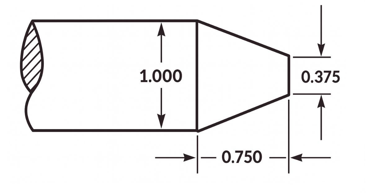
The knurling operation is started by determining the location and length of the knurl, and then setting the machine for knurling. A slow speed is needed with a medium feed. Commonly, the speed is set to 60 to 80 RPM, whilst the feed is best from 0.015 to 0.030 inch per revolution of the spindle. The knurling tool must be set in the tool post with the axis of the knurling head at centre height and the face of the knurls parallel with the work surface. Check that the rollers move freely and are in good cutting condition; then oil the knurling tool cutting wheels where they contact the workpiece. Bring the cutting wheels (rollers) up to the surface of the work with approximately 1/2 of the face of the roller in contact with the work.
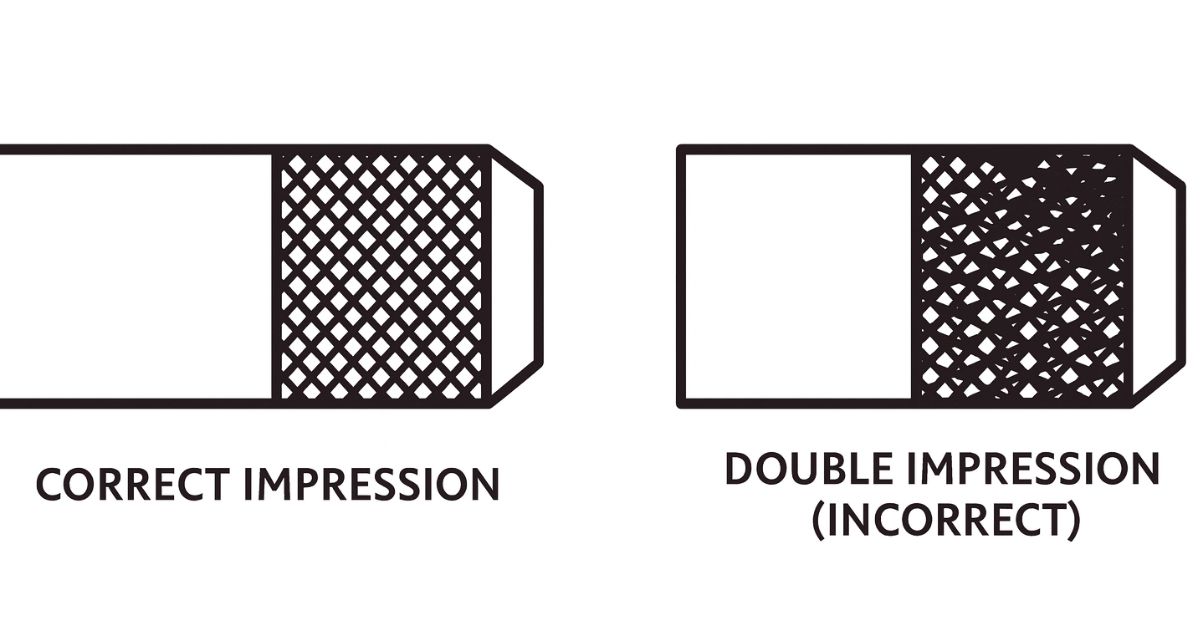
If the face of the roller is placed in this manner, the initial pressure that is required to start the knurl will be lessened and the knurl may cut smoother. Apply oil generously over the area to be knurled. Start the lathe whilst forcing the knurls into the work about 0.010 inch. As the impression starts to form, engage the carriage feed lever. Observe the knurl for a few revolutions and shut off the machine. Check to see that the knurl is tracking properly, and that it is not on a "double track".
Reset the tool if needed; otherwise, move the carriage and tool back to the starting point and lightly bring the tool back into the previously knurled portion. The rollers will align themselves with the knurled impressions. Force the knurling tool into the work to a depth of about 1/64 inch and simultaneously engage the carriage to feed towards the headstock. Observe the knurling action and allow the tool to knurl to within 1/32 inch of the desired end of cut, and disengage the feed. Hand feed to the point where only one-half of the knurling wheel is off the work, change the feed direction towards the tailstock and force the tool deeper into the work.
Engage the carriage feed and cut back to the starting point. Stop the lathe and check the knurl for completeness. Never allow the knurling tool to feed entirely off the end of the work, or it could cause damage to the work or lathe centres. The knurl is complete when the diamond shape (or straight knurl) is fully developed. Excessive knurling after the knurl has formed will wear off the full knurl and ruin the work diameter. Move the tool away from the work as the work revolves and shut off the lathe. Clean the knurl with a brush and then remove any burrs with a file.
Special Knurling Precautions
Never stop the carriage whilst the tool is in contact with the work and the work is still revolving as this will cause wear rings on the work surface. Check the operation to ensure that the knurling tool is not forcing the work from the centre hole. Keep the work and knurling tool well oiled during the operation. Never allow a brush or rag to come between the rollers and the work or the knurl will be ruined.
Drilling with the Lathe
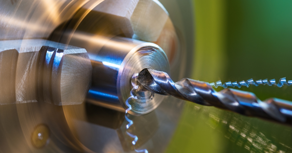
Frequently, holes will need to be drilled using the lathe before other internal operations can be completed, such as boring, reaming, and tapping. Although the lathe is not a drilling machine, time and effort are saved by using the lathe for drilling operations instead of changing the work to another machine. Before drilling the end of a workpiece on the lathe, the end to be drilled must be spotted (centre-punched) and then centre-drilled so that the drill will start properly and be correctly aligned. The headstock and tailstock spindles should be aligned for all drilling, reaming, and tapping operations in order to produce a true hole and avoid damage to the work and the lathe. The purpose for which the hole is to be drilled will determine the proper size drill to use. That is, the drill size must allow sufficient material for tapping, reaming, and boring if such operations are to follow.
The correct drilling speed usually seems too fast due to the fact that the chuck, being so much larger than the drill, influences the operator's judgement. It is therefore advisable to refer to a suitable table to obtain the recommended drilling speeds for various materials.
Supporting Drills in the Tailstock
Methods of supporting the twist drill in the tailstock can vary. Straight shank drills are usually held in a drill chuck, which is placed in the taper socket of the tailstock spindle. Combination drill and countersinks (centre drills), counterbores, reamers, taps, and other small shank cutters can also be supported in this way.
Tapered-shank twist drills may be held directly in the tailstock tapered spindle as long as a good fit exists. If the drill shank is not the correct size, then a drill socket or sleeve may be used in the tailstock spindle.
A twist drill holder is used to support large twist drills with the tailstock centre. The drill is inserted into the holder and the tailstock centre is placed in the centre hole which is located at the rear of the drill holder. The holder will rest on the cross slide or compound rest and must be supported by hand until it is held secure by pressure between the tailstock and headstock. When using this method, never withdraw or loosen the tailstock spindle whilst the lathe is rotating or the workpiece can be thrown out at the operator. Always stop the machine before attempting to withdraw the twist drill.
Another method of supporting a large twist drill in the tailstock is to fasten a lathe dog to the drill shank and support the rear of the drill with the tailstock centre in the centre hole in the tang of the drill.
Supporting Drills in the Headstock
The drill can also be held and rotated in the headstock with the work held stationary against the tailstock. Straight shank twist drills are supported in the headstock by a drill chuck or collet which is mounted in the headstock spindle. A universal or independent jaw chuck can also be used to hold and turn twist drills if a headstock drill chuck is not available. Tapered shank twist drills can be mounted in the headstock by using a special adapter, such as a sleeve with an internal taper to hold the tapered drill, whilst the outside of the sleeve is made to fit into the headstock spindle.
Mounting Work for Drilling
If the work is to be rotated and the twist drill will be fed into the end of the work, the work should be mounted in a chuck, on a faceplate, or in a collet. The centre of the hole to be drilled should be accurately marked and punched as described for drilling setups. Always start holes by using a centre drill, since this method will be the most accurate and the most efficient. Centre-drill by rotating the spindle at computed drill speed and gently bringing the point of the centre drill into the end of the work until the proper depth is reached.
If the twist drill is to be rotated by the headstock spindle and the workpiece is to be supported by a V-centre mounted in the tailstock, the work should be carefully positioned by hand and the drill moved lightly into contact with the workpiece before starting the lathe. The workpiece must be well supported during drilling operations to prevent the work from being thrown from the lathe or rotating with the drill.
Drilling Operations
To start the drilling operation, compute the correct RPM for the drill and set the spindle speed accordingly. Ensure the tailstock is clamped down on the lathe ways. The feed is controlled by turning the tailstock handwheel. The graduations on the tailstock spindle are used to determine the depth of cut.
If a large twist drill is used, it should be proceeded by a pilot drill, the diameter of which should be wider than the larger drill's web. Use a suitable cutting fluid whilst drilling. Always withdraw the drill and brush out the chips before attempting to check the depth of the hole. If the drill is wobbling and wiggling in the hole, use a tool holder turned backwards to steady the drill. Always use a drill that is properly ground for the material to be drilled. Use care when feeding the drill into the work to avoid breaking the drill off in the work. The drill should never be removed from the work whilst the spindle is turning because the drill could be pulled off the tailstock spindle and cause injury or damage.
Boring with the Lathe
Boring is the enlarging and truing of a hole by removing material from internal surfaces with a single-point cutter bit. On the lathe, boring is accomplished in either of these two methods:
- Mounting the holder and boring tool bar with cutter bit on the tool post and revolving the workpiece.
- Mounting the workpiece in a fixed position to the carriage and revolving the boring tool bar and cutter bit in a chuck attached to the headstock spindle. (This is a special process and not used in most machine shops).
Mounting Workpiece for Boring
The workpiece may be supported in a chuck or fastened to a faceplate for boring operations depending on the material to be machined. When boring is to be performed on the ends of long stock, the workpiece is mounted in a chuck and a steady rest is used to support the right end near the cutter bit. Some boring operations require the use of special chuck-mounted mandrels to hold workpieces that cannot be successfully mounted otherwise.
Purpose for Boring
Boring is necessary in many cases to produce accurate holes. Drilled holes are seldom straight due to imperfections in the material which cause drills to move out of alignment. Therefore, where accuracy is important, drilled holes are usually made undersize and then bored or reamed to the proper dimensions. Boring is also useful in truing large holes in flat material. In this case, the hole is cut undersize using a bandsaw or trepanning tool and is trued to proper dimensions by boring.
Boring Cutter Bit Setup

The cutter bit used for boring is similar to that used for external turning on the lathe. The bit is usually held in a soft or semi-soft bar called a boring tool bar. The boring tool bar is supported by a cutting tool holder which fits into the lathe tool post. Boring tool bars are supplied in several types and sizes for holding different cutter bits. The bit is supported in the boring tool bar at a 90°, 30°, or 45° angle, depending upon the nature of the workpiece being bored. Most general boring is accomplished with a 90° cutter bit. The bit is mounted at a 30° or 45° angle to the axis of the boring tool bar when it is necessary to cut up to the bottom of a hole or finish the side of an internal shoulder. It is desirable that the boring tool bar be as large as possible without interfering with the walls of the hole. The cutter bit should not extend far beyond the boring tool bar and the bit should be secured in the bar, yet not have the shank-end protrude far from the bar.
The cutter bits used for boring are shaped like left-hand turning and facing cutter bits. Greater attention must be given to the end clearance angle and the back rake angle because of the curvature of the hole.
The boring tool bar should be clamped as close to the holder and tool post as possible considering the depth of boring to be done. The bar will have a tendency to spring away from the workpiece if the bar overhangs the tool post too far. If deep boring is to be performed, it will be necessary that the bar be as thick as possible to counteract this springing tendency.
Straight Boring Operation
The cutter bit is positioned for straight boring operations with its cutting edge set slightly above centre. Depending on the rigidity of the setup, the boring tool will have a tendency to spring downward as pressure is applied to the cutting edge. By setting the cutter slightly above centre, compensation has been made for the downward spring and the cutter will actually be positioned on the exact centre of the workpiece during machining operations. The cutting edge faces forward for most operations so the lathe can turn in its normal counterclockwise direction. If it becomes necessary to position the cutter bit against the rear wall of the hole for a special operation, a right-hand turning cutter bit is used and the spindle rotation is reversed.
Position the cutter bit so that the cutting edge is immediately to the right of the workpiece and clears the wall of the hole by about 1/16 inch. Traverse the carriage by hand, without starting the lathe, to move the cutter bit and boring tool bar into the hole to the depth of the intended boring and out again to determine whether there is sufficient clearance to prevent the back of the cutter bit and the boring tool bar from rubbing the inside of the hole. When the clearance is satisfactory, position the cutter bit to the right of the workpiece ready for the first cut. Use the micrometer carriage stop to control the depth of tool travel.
The same speeds recommended for straight turning should be used for straight boring. Feeds for boring should be considerably smaller than feeds used for straight turning because there is less rigidity in the setup. Decrease the depth of cut for each pass of the tool bit for the same reason. It is often advisable to feed the cutter bit into the hole to the desired depth and then reverse the feed and let the cutter bit move out of the hole without changing the depth of feed. It is also good practice to take a free cut every several passes to help eliminate bell mouthing of the workpiece. This practice will correct any irregularities caused by the bit or boring tool bar springing because of the pressure applied to the bit.
Tapping and Hand Die Threading
The lathe can be used as a device to hold and align a tap or hand die to cut internal or external threads quickly for threads that do not require a high degree of accuracy or a fine finish.
Hand Tapping on the Lathe
Tapping can be done on the lathe by power or by hand. Regardless of the method, the hole must be drilled with the proper sized tap drill and chamfered at the end. The shank end of the tap is supported by the tailstock centre. A slight pressure is maintained against the tap to keep its centre hole on the centre and to help the cutting teeth of the tap engage the work.
The work will rotate when tapping using lathe power. Use a very slow spindle speed (10 to 30 RPM) and plenty of cutting fluid or coolant. Install a tap and reamer wrench on the end of the tap to keep it from turning. Support the wrench on the compound rest. Power is not recommended for taps under 1/2 inch in diameter or when tapping steel. Ensure that the tap wrench handle contacts the compound rest before engaging power or the end of the handle will whip around and could crush a finger or cause other injury or damage. Do not attempt to start the tap into the hole with the work revolving. Always keep the tap snug in the centre hole to prevent the tap from coming out of alignment and ruining the threads.
The setup for hand tapping in a lathe is similar to that used in power tapping. The headstock chuck is held steady and not rotated. The tap is turned by using an adjustable wrench. Lock the lathe gears so that the headstock will not move when using a large tap. Back off the tap frequently when tapping to break the chips and allow for a clean thread.
Hand Die Threading on the Lathe
Die threading on a lathe is very similar to tapping on a lathe, except that the die is aligned perpendicular to the work axis by pressure exerted against the back surface of the die. This pressure can be exerted by means of a drill pad, by using the tailstock spindle, or by using the head of the drill chuck for small dies. Die threading can be done using power or by hand, using the same procedures as tapping. Power can be used to remove the die from the work if the die stock handle is swung to the opposite side and low reverse power is used. It is difficult to cut very coarse threads with a die because of the great amount of force needed to turn the die. It is advisable to open up the die to its full width, rough-cut the threads, and then close up the die and go over the threads for a finished size. Always use a lubricant or coolant for this operation.
Reaming on the Lathe
Reamers are used to finish drilled holes or bores quickly and accurately to a specified diameter. When a hole is to be reamed, it must first be drilled or bored to within 0.004 to 0.012 inch of the finished size since the reamer is not designed to remove much material.
Reaming with a Machine Reamer
The hole to be reamed with a machine reamer must be drilled or bored to within 0.012 inch of the finished size so that the machine reamer will only have to remove the cutter bit marks.
The workpiece is mounted in a chuck at the headstock spindle and the reamer is supported by the tailstock in one of the methods described for holding a twist drill in the tailstock. The lathe speed for machine reaming should be approximately one-half that used for drilling.
Reaming with a Hand Reamer
The hole to be reamed by hand must be within 0.005 inch of the required finished size. The workpiece is mounted to the headstock spindle in a chuck and the headstock spindle is locked after the piece is accurately setup. The hand reamer is mounted in an adjustable tap and reamer wrench and supported with the tailstock centre. As the wrench is revolved by hand, the hand reamer is fed into the hole simultaneously by turning the tailstock handwheel.
The reamer should be withdrawn from the hole carefully, turning it in the same direction as when reaming. Never turn a reamer backward. Never use power with a hand reamer or the work could be ruined.
Filing and Polishing on the Lathe
Filing and polishing are performed on the lathe to remove tool marks, reduce the dimension slightly, or improve the finish.
Filing on the Lathe
Mill files are generally considered best for lathe filing. The bastard cut mill type hand file is used for roughing and the second cut mill-type hand file for the finer class of work. Other types such as the round, half-round, and flat hand files may also be used for finishing irregular shaped workpieces. Never use a file without a handle.
For filing ferrous metals, the lathe spindle speed should be four or five times greater than the rough turning speed. For filing non-ferrous metals, the lathe spindle speed should be only two or three times greater than the roughing speed. Too slow a speed may cause the workpiece to be filed out of round, whilst too high a speed will cause the file to slide over the workpiece, dulling the file and glazing the piece.
The file is held at an angle of about 10° to the right and moved with a slow sliding motion from left to right so that the teeth will have a shearing action. The direction of stroke and angle should never be the opposite, as this will cause chatter marks on the piece. The file should be passed slowly over the workpiece so that the piece will have made several revolutions before the stroke is completed. The pressure exerted on the file with the hands should be less than when filing at the bench. Since there are less teeth in contact with the workpiece, the file must be cleaned frequently to avoid scratching.
Since filing should be used for little more than to remove tool marks from the workpiece, only 0.002 to 0.005 inch should be left for the filing operation.
Polishing on the Lathe
Polishing with either abrasive cloth or abrasive paper is desirable to improve the surface finish after filing. Emery abrasive cloth is best for ferrous metals whilst abrasive paper often gives better results on non-ferrous materials. The most effective speed for polishing with ordinary abrasives is approximately 5,000 feet per minute. Since most lathes are not capable of a speed this great for an average size workpiece, it is necessary to select as high a speed as conditions will permit.
In most cases the abrasive cloth or paper is held directly in the hand and applied to the workpiece, although it may be tacked over a piece of wood and used in the same manner as a file. Improvised clamps may also be used to polish plain round work.
Since polishing will slightly reduce the dimensions of the workpiece, 0.00025 to 0.0005 inch should be allowed for this operation. Note that the ends of the strip are separated when holding the abrasive strip when polishing. This prevents the strip from grabbing and winding around the work, which could pull the operator's hand into the work. Move the polishing strip slowly back and forth to prevent material building up on the strip which causes polishing rings to form on the work. To produce a bright surface, polish the work dry. To produce a dull satin finish, apply oil as the polishing operation is in progress.
Eccentric Work on the Lathe
Eccentric work is work that is turned off centre, or not on the normal centre axis. An engine crankshaft is a good example of an eccentric workpiece. Crankshafts normally have a main centre axis, called a main journal, and offset axes, which produce the throw and the eccentric diameters of the mechanism. An eccentric shaft may have two or more diameters and several different centre axes. The amount of eccentricity, or half of the throw, is the linear distance that a set of centre holes has been offset from the normal centre axis of the workpiece. Eccentric turning on the lathe is used for the following eccentric turning situations:
- When the throw is large enough to allow all centres to be located on the workpiece at the same time.
- When the throw is too small to allow all centres to fit into the end of a workpiece at the same time. (The centre drilled holes are too large.)
- When the throw is so great that all centres cannot be located on the work, or in other words, a throw larger than the largest diameter of the workpiece. (This type of crank is usually made in separate pieces and connected together, since the cost of wasted material would be too great if constructed from one piece on the lathe).
Turning an Eccentric with Centre Holes
Before an eccentric workpiece can be machined, it is necessary to centre-drill both ends of the workpiece, including the offset centres. If the workpiece is large enough to position all centre axes on the work at the same time, the machining operation will be simple and easy.
First determine the stock required by adding the throws plus 1/8 inch for machining. Face the work to length in a chuck. Remove the piece and apply layout dye to both ends. Mount the work in a V-block and, using a surface plate and vernier height scriber, lay out the normal centre axis and the offset centre axes on both ends. Accurately prick punch the intended centres, check for accuracy, and then enlarge the punch marks with a centre punch. Centre-drill both sets of centre punch marks by using a milling machine, a drilling machine, or the four-jaw independent chuck of the lathe with a dial indicator to line up the centres. Mount the work in the lathe between centres and turn the largest diameter first. If all diameters are the same, turn the middle diameter journal first. After turning the centre journal down to the required diameter, remount the work in an offset centre hole and machine the throw diameter to the finished size.
Additional throws are machined in the same manner. Throw positions may be started by cutting with a parting tool to establish the shoulders, which may aid the turning operation. The tool bit selected will depend on the material to be machined and on the depth of cut desired.
Turning an Eccentric with Close Centre Holes
If turning an eccentric that has the different centres placed too close together, a different procedure should be used. Cut the stock 3/4 inch oversized and just face both ends to clean up the saw cuts. Lay out and centre-drill the normal centre axis and turn down those diameters on the centre axis with the work mounted between centres. Remove the work and remount into a chuck. Face both ends to the required length and centre-drill the offset centres. Remount the work between these centres and machine the eccentric diameters to size. For eccentric work that has a limited distance between each centre, this method is safer than trying to use a very shallow centre-drilled hole to hold the work between centres.
Turning an Eccentric Using Throw Plates
If the lathe is to be used to turn a crank with a great throw, or a throw that is greater than normally machined on a lathe, special throw plates must be fabricated to hold the ends of the work whilst turning. The special throw plates will be used as support blocks to enable the offset centre holes to be machined into the throw plates and allow for eccentric turning. Although this may solve the problem of eccentric turning, it is not recommended for normal lathe operations. Special crankshaft turning and grinding equipment is available for this type of machining.
Recessing Drilled and Bored Holes
General
Recessing, sometimes called channelling or cambering, is the process of cutting a groove inside of a drilled, bored, or reamed hole. Recesses are usually machined to provide room for the tool runout needed for subsequent operations such as internal threading.
A boring bar and holder may be used as a recessing tool, since recessing tools have the same tool angles and are similar in shape to boring tools. A high-speed steel cutting tool bit, ground with a square nose, makes a satisfactory tool for cutting small chambers. The sides of the tool bit taper in from the cutting edge so that the nose of the tool is the widest part. The tool bit must extend from the holder a distance slightly greater than the depth of the chamber to prevent the holder from rubbing the bore of the work.
Machining a Recess
To cut a recess, set up the lathe as in a boring operation. Reference the face of the tool bit to the face of the work; then move the tool bit forward the required distance to the recess by using the micrometer stop or by using the compound rest graduated collar. The compound rest must be set parallel with the ways of the bed for this method. Add the width of the tool bit into the measurement or the recess will not be cut correctly. Position A is the tool aligning to the work, position B is set over to the front shoulder of the recess, and position C is the set over to the back of the recess. Use the cross slide graduated collar to measure the distance to move the tool bit towards the operator, inside of the hole. Spindle speed may have to be reduced due to the shape of the tool bit causing chatter on the work. After cutting the recess, use inside callipers to check the diameter.
Lathe Tool Post Grinder
General
The tool post grinder is a portable grinding machine that can be mounted on the compound rest of a lathe in place of the tool post. It can be used to machine work that is too hard to cut by ordinary means or to machine work that requires a very fine finish. The grinder must be set on centre. The centring holes located on the spindle shaft are used for this purpose. The grinding wheel takes the place of a lathe cutting tool. It can perform most of the operations that a cutting tool is capable of performing. Cylindrical, tapered, and internal surfaces can be ground with the tool post grinder. Very small grinding wheels are mounted on tapered shafts known as quills to grind internal surfaces.
Selection of Grinding Wheels and Speeds
The grinding wheel speed is changed by using various sizes of pulleys on the motor and spindle shafts. An instruction plate on the grinder gives both the diameter of the pulleys required to obtain a given speed and the maximum safe speed for grinding wheels of various diameters. Grinding wheels are safe for operation at a speed just below the highest recommended speed. A higher than recommended speed may cause the wheel to disintegrate. For this reason, wheel guards are furnished with the tool post grinder to protect against injury. Always check the pulley combinations given on the instruction plate of the grinder when you mount a wheel. Be sure that the combination is not reversed, because this may cause the wheel to run at a speed far in excess of that recommended. During all grinding operations, wear goggles to protect your eyes from flying abrasive material.
Dressing the Grinding Wheel
The grinding wheel must be dressed and trued. Use a diamond wheel dresser to dress and true the wheel. The dresser is held in a holder that is clamped to the drive plate. Set the point of the diamond at centre height and at a 10° to 15° angle in the direction of the grinding wheel rotation. The 10° to 15° angle prevents the diamond from gouging the wheel. Lock the lathe spindle by placing the spindle speed control lever in the low RPM position.
Remove the diamond dresser holder as soon as the dressing operation is completed. Bring the grinding wheel in contact with the diamond by carefully feeding the cross slide by hand. Move the wheel clear of the diamond and make a cut by means of the cross slide. The maximum depth of cut is 0.002 inch. Move the wheel slowly by hand back and forth over the point of the diamond. Move the carriage if the face of the wheel is parallel to the way of the lathe. Move the compound rest if the face of the wheel is at an angle. Make the final depth of cut of 0.0005 inch with a slow, even feed to obtain a good wheel finish.
Before you begin the grinding operation, cover the ways with a heavy piece of paper or use a shallow pan of water placed on the ways to collect the grinding dust that will accumulate from the grinding. This is to ensure none of the grinding burns to the ways or gets under the carriage which will cause the lathe premature wear. If you use a piece of paper, pay close attention that the sparks from the grinding operation do not cause the paper to ignite. If you use a shallow pan of water, make sure water is not spilled on the ways of the lathe. After all grinding operations, thoroughly clean and oil the lathe to remove any grinding dust that the paper or pan of water missed.
Grinding Feeds, Speeds, and Depth of Cuts
Rotate the work at a fairly low speed during the grinding operations. The recommended surface foot speed is 60 to 100 FPM. The depth of cut depends upon the hardness of the work, the type of grinding wheel, and the desired finish.
Never take grinding cuts deeper than 0.002 inch. Use a fairly low rate of feed. You will soon be able to judge whether the feed should be increased or decreased. Never stop the rotation of the work or the grinding wheel whilst they are in contact with each other.
Marking Position of Lathe Centres
Tool post grinders are often used to refinish damaged lathe centres. If the lathe is to be used for turning between centres in the near future, grind the tailstock centre first, then the headstock centre. Leave the headstock centre in position for the turning operation. This method provides the greatest degree of accuracy. If you must remove the headstock centre in order to perform other operations, marks placed on the headstock centre, the sleeve, and the centre will enable you to install them in the same position they were in when the centre was ground. This will ensure the greatest degree of accuracy for future operations involving turning work between centres.
Setup for Grinding Lathe Centres
To refinish a damaged lathe centre, you should first install headstock and tailstock centres after ensuring that the spindle holes, drill sleeves, and centres are clean and free of burrs. Next, position the compound rest parallel to the ways; then, mount the tool post grinder on the compound rest. Make sure that the grinding wheel spindle is at centre height and aligned with the lathe centres. Move the compound rest 30° to the right of the lathe spindle axis. Mount the wheel dresser, covering the ways and carriage with rags to protect them from abrasive particles. Wear goggles to protect your eyes.
Grinding Lathe Centres
Start the grinding motor. Turn it on and off alternately, but let it run a bit longer each time, until the abrasive wheel is brought up to top speed. Dress the wheel, feeding the grinder with the compound rest. Then move the grinder clear of the headstock centre and remove the wheel dresser. Set the lathe for the desired spindle speed and engage the spindle. Pick up the surface of the centre. Take a light depth of cut and feed the grinder back and forth with the compound rest. Do not allow the abrasive wheel to feed entirely off the centre. Continue taking additional cuts until the centre cleans up. To produce a good finish, reduce the feed rate and the depth of cut to 0.0005. Grind off the centre's sharp point, leaving a flat with a diameter about 1/32 inch. Move the grinder clear of the headstock and turn it off.
Milling on the Lathe
Milling operations may be performed on the lathe by using the lathe milling fixture. The lathe milling fixture complements other attachments and adds to the basic capabilities of the machine shop. Many milling operations can be accomplished by using the milling fixture.
Using Micrometer Carriage Stop
The micrometer carriage stop is used to accurately position the lathe carriage. Move the carriage so that the cutting tool is approximately positioned. Clamp the micrometer carriage stop to the ways of the lathe, with the spindle in contact with the carriage. The spindle of the micrometer carriage stop can be extended or retracted by means of the knurled adjusting collar. The graduations on the collar, which indicate movement in thousandths of an inch, make it possible to set the spindle accurately. Next, bring the carriage in contact with the micrometer spindle again. The carriage can be accurately positioned within 0.001 inch. This is very useful when you are facing work to length, machining shoulders to an exact length, or accurately spacing internal and external grooves. After making a cut, bring the tool back to the start of the cut by means of the carriage stop. This feature is very useful when you must remove a tool, such as the internal recessing tool, from the hole to take measurements and then reposition it to take additional cuts. Always bring the carriage into contact with the stop by hand. Use power feed to bring the carriage within 1/32 inch of the stop. Move the carriage by hand the remaining distance.
Using Steady and Follower Rests
General
The steady rest consists of a frame and three adjustable jaws which support the work. One purpose of the steady rest is to prevent springing or deflection of slender, flexible work; another is to furnish auxiliary support for the work to permit heavy cuts to be made; a third is to support work for drilling, boring, or internal threading. The over arm containing the top jaw can be unfastened and swung out of the way so that identical pieces can be removed and replaced without adjusting the jaws.
Bearing Surface
A bearing surface must be provided for the steady rest jaws. The bearing surface is usually machined directly on the work. When the work is too small in diameter to machine the bearing surface or shaped so that it would be impractical to machine one, you can use a cathead to provide the bearing surface. The cathead has a bearing surface, a hole through which the work extends, and adjusting screws. The adjusting screws fasten the cathead to the work. They are also used to align the bearing surface so that it is concentric to the work axis. Use a dial indicator to ensure concentricity.
Setting up the Steady Rest
To setup the rest, first machine and polish the portion of the work that is to be used as the bearing surface. Clean the portion of the ways where the steady rest is to be mounted, place the steady rest on the ways and clamp loosely. Open the top of the steady rest and place the workpiece in the chuck with the bearing surface over the adjustable jaws. Clamp the steady rest securely to the ways. Close the top of the steady rest and adjust the jaws to the workpiece. There should be 0.001 inch clearance between the jaws and the workpiece. Tighten the locking screws on the adjustable jaws. Lubricate the bearing surface generously with a heavy oil before turning the lathe on. Proceed with the machining operation. Continuously watch the bearing surface and the adjustable jaws to ensure a film of heavy oil is between them. As the machining operation continues, also check the bearing surface and adjustable jaws as when the workpiece heats up it will expand, closing the distance between the jaws and the workpiece.
Using Steady Rest with Headstock Centre
When it is not possible to hold the work in the chuck, you can machine with one end supported by the headstock centre and the other end supported by the steady rest. Use a leather strap or rawhide thong to tie the work to the driveplate and to prevent it from moving off the headstock centre. Mount the work between centres and machine the bearing surface. Set up the steady rest. With the work mounted between the centres, tie the lathe dog, then remove the tailstock centre and perform the necessary machining.
Using the Follower Rest
Long slender shafts that tend to whip and spring whilst they are being machined require the use of a follower rest. The follower rest is fastened to the carriage and moves with the cutting tool. The upper jaw prevents the work from climbing the cutting tool. The lower jaw prevents the work from springing away from the cutting tool. The follower rest jaws are adjusted in the same manner as steady rest jaws. The follower rest is often used when long, flexible shafts are threaded. At the completion of each threading cut, remove any burrs that may have formed to prevent them from causing the work to move out of alignment.