MAC AFRIC Multifunctional Electrical Round & Square Pipe Bender Operations & Troubleshooting Manual M
MAC AFRIC Multifunctional Electrical Round & Square Pipe Bender - Complete Operations Guide
MAC AFRIC Multifunctional Electrical Round & Square Pipe Bender — Operations & Troubleshooting Manual
Model: MAC AFRIC Multifunctional Electrical Round & Square Pipe Bender
SKU: GPIPEB005
Supplier: Adendorff Machinery Mart
Revision: 1.0 (22 Aug 2025)
1) Purpose & Scope
This manual explains safe setup, operation, maintenance, and troubleshooting for the MAC AFRIC Multifunctional Electrical Round & Square Pipe Bender. It also includes best‑practice bending tips for round and square tubing and a quick reference for dies and capacities.
Read first. Improper setup or die selection can cause poor bends, machine damage, or injury. Only trained operators should use this machine.
2) Safety Information
- Electrical: 230 V @ 50 Hz supply. Connect to a dedicated circuit with proper earthing and an RCD/ELCB. Isolate power before changing dies, cleaning, or servicing.
- Pinch/Crush hazards: Keep hands, clothing, and jewelry clear of rollers, dies, and the drive chain area during operation.
- PPE: Safety glasses/face shield, close‑fitting gloves (no loose cuffs), steel‑toe shoes, and hearing protection as needed.
- Workpiece safety: Deburr cut ends; sharp burrs can catch during rolling. Confirm wall thickness is within the recommended range for the selected die and material.
- Lifting: The machine is heavy. Use mechanical assistance and safe lifting technique. Secure the machine to a level floor before use.
- Hot surfaces: Extended operation may warm dies/rollers. Allow to cool before handling.
- No modification: Do not alter guards, electricals, or control logic.
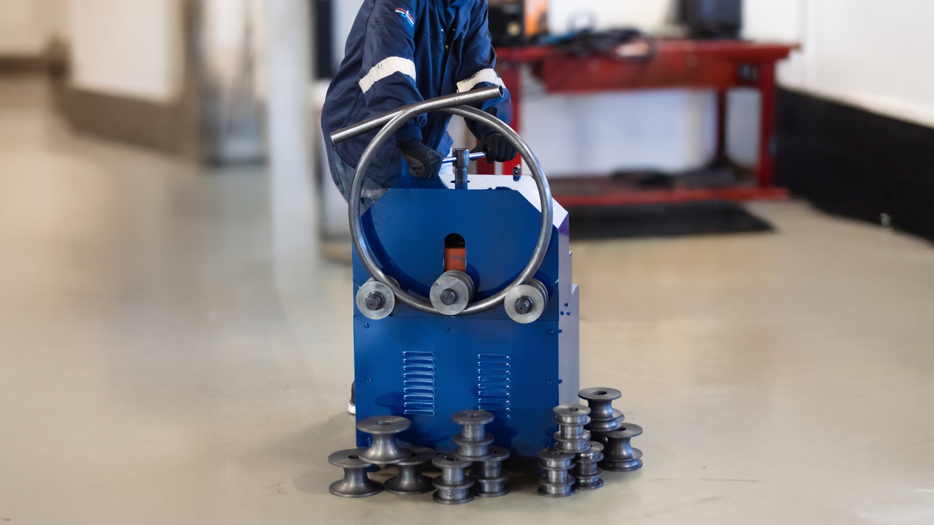
3) Machine Overview
- Configuration: Three‑roller, electrically driven, hand‑adjustable shafts (two main shafts + one driven). Suitable for making large‑radius arcs and complete rings in round and square tube.
- Typical applications: Greenhouses, gates/railings, decorative arches, general metal frameworks.
3.1 Controls & Major Components
- Main power switch / emergency‑off
- Forward/Reverse selector for feed direction
- Motor/Drive (under guard)
- Upper adjusting wheel/handwheels for changing the working radius
- Side guides (if fitted) for tracking long workpieces
- Die/roller sets (interchangeable round and square formers)
- Base & anchor points for floor mounting
Note: Actual control labels may vary by production batch; function remains the same.
4) Technical Specifications (Quick Reference)
- Supply: 230 V @ 50 Hz
- Motor: 1.5 kW, ~1400 rpm
- Bending radius range: ~320 mm to ~1520 mm (measured to centerline)
- Wall thickness capacity (typical): 0.5–2.0 mm depending on size/material (see tables)
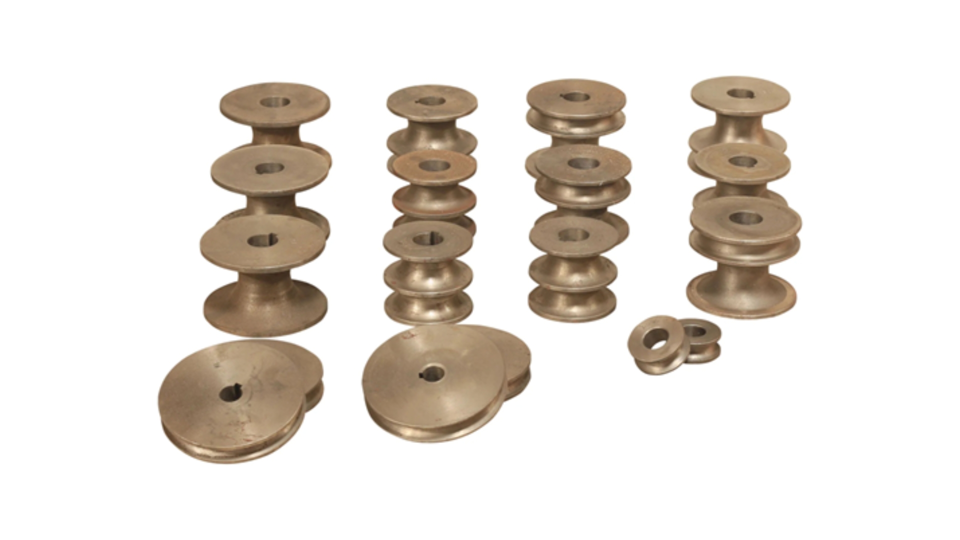
- Round formers (included range): 16, 19, 22, 25, 32, 38, 51, 63, 76 mm
- Square formers (included range): 16, 19, 22, 25, 30, 38, 40, 50 mm
- Packaging (for logistics): 73 × 63 × 103 cm; approx. 260 kg gross
Good‑practice radius rule: Minimum recommended bend diameter ≈ ≥ 20× tube OD (or across‑flats for square) to limit flattening on non‑mandrel, roll‑type benders.
5) What's in the Box
- Main machine assembly (pre‑guarded drive)
- One set of round formers (see sizes above)
- One set of square formers (see sizes above)
- Side panels/guards (fitted)
- Basic tool kit for die changes (spanners/allen keys)
Optional/Spare: Replacement die sets are available as complete round or square packs.
6) Installation & Commissioning
- Positioning: Place on a flat, rigid floor with ≥ 1.5 m clear space on the feed and exit sides. Orient so long stock can run through unobstructed.
- Anchoring: Mark and drill anchor points. Use M12 (or as supplied) expansion anchors. Tighten after final leveling.
- Electrical: Connect to a dedicated 230 V, 50 Hz circuit with earth. Fit upstream 20 A breaker (typical) and RCD. Avoid long undersized extension leads.
- Inspection before power‑up:
- Guards secure; no shipping inserts in the roller area
- Dies correctly seated and locked
- Adjusters move smoothly; no excessive play
- Chain/belt at correct tension
- Dry run: With no material, briefly jog Forward/Reverse to verify rotation and stop function.
7) Die Selection & Setup
7.1 Selecting the Correct Die Set
- Match size to tube OD (round) or across‑flats (square). Using a die larger than the tube can cause tracking errors and flattening; too small can mark or buckle.
- Material & wall thickness: Ensure your tube wall matches the Recommended Wall Thickness tables in §8. If in doubt, choose a larger radius or thicker wall.
7.2 Changing Dies (General Procedure)
- Isolate power and wait for motion to stop.
- Remove guards as required.
- Loosen the die retaining fastener(s) and withdraw the existing dies.
- Clean the shaft taper/key and the die bore. Apply a light film of oil.
- Install the new die set (all three rollers must correspond to the same size/profile).
- Torque/secure fasteners; re‑fit guards.
- Run a short no‑load test.
Tip: Keep round and square die sets stored in labeled trays. Mix‑matching profiles reduces accuracy and can damage work.
Additional Note on Die Usage During Bending
Please note, while forming tubing, the shape and geometry change under load, exerting pressure onto the internal wall of the selected die. This can cause premature wear, damage, or breakage to the die. To minimize risk, it is recommended to select and use a larger die during the bending process, as the desired angle is progressively achieved through multiple forming passes rather than excessive pressure in a single pass.
8) Capacity & Recommended Wall Thickness
The following guidelines help minimize ovality and kinks for non‑mandrel roll bending.
8.1 Round Tube — Recommended Wall Thickness (Stainless / Mild Steel)
| Tube Size (mm) | Stainless Steel (mm) | Mild Steel (mm) |
|---|---|---|
| 16 | 0.5 | 0.8 |
| 19 | 0.8 | 1.0 |
| 22 | 1.0 | 1.2 |
| 25 | 1.0 | 1.2 |
| 32 | 1.2 | 1.5 |
| 38 | 1.5 | 1.5 |
| 51 | 1.5 | 1.8 |
| 63 | 2.0 | 2.3 |
| 76 | 2.0 | 2.3 |
8.2 Square Tube — Recommended Wall Thickness (Stainless / Mild Steel)
| Tube Size (mm) | Stainless Steel (mm) | Mild Steel (mm) |
|---|---|---|
| 16 | 0.5 | 0.8 |
| 19 | 0.8 | 1.0 |
| 22 | 1.0 | 1.2 |
| 25 | 1.0 | 1.2 |
| 30 | 1.2 | 1.5 |
| 38 | 1.5 | 1.5 |
| 40 | 1.5 | 1.8 |
| 50 | 1.5 | 1.8 |
Rule‑of‑thumb bending diameter: ≥ 20× the tube size (OD or AF) is a practical minimum on this style of machine; larger diameters improve surface finish and geometry.
9) Operating Procedures
9.1 General Rolling (Arcs & Rings)
- Prepare stock: Cut to length with square ends; deburr inside/outside. Mark a centerline if you must keep orientation consistent (square tube).
- Set initial radius: Rotate the adjuster to bring the top roller down (or central roller up, per design) to achieve a starting radius within the machine's ~320–1520 mm range.
- Test pass: Power ON. Feed the tube through with the guide end flat against the entry rollers; use Forward to pull the work. Support the exit end at all times.
- Progressive bending: After each pass, increase the forming pressure a small amount and repeat until the desired curvature is achieved.
- Check roundness: For circles, overlap the ends and check chord gap; adjust pressure as needed to close the ring with minimal flat.
- Reverse feed: Use Reverse to back the work out if you've over‑rolled. Reduce pressure before reversing.
9.2 Bending Square Tube Cleanly
- Orientation: Keep the same face against the reference guide throughout to avoid twist. Mark one face as "outboard."
- Avoid wrinkling: Use the largest feasible radius and ensure wall thickness meets §8.2.
- Tracking: Lightly pinch the entry side with side guides (if fitted) to prevent walk.
9.3 Closing a True Circle
- Calculate target circumference from desired centerline diameter.
- Form to ~95% of curvature, then make small adjustments while checking overlap.
- For welded rings, leave a small straight (~1–2× tube size) at the joint to aid clamping; blend out after welding with a light corrective pass.
10) Quality Tips & Common Defects
- Flattening/Ovality: Increase radius, increase wall thickness, or use a die closer to tube size; ensure equal pressure left/right.
- Buckling/Wrinkles (inside radius): Excessive pressure or too‑tight radius; reduce penetration and make more passes; verify wall thickness is adequate.
- Corkscrew twist (square tube): Inconsistent orientation or side pressure; add/alleviate side guide bias; mark and maintain one face orientation.
- Spiral arc: Entry not square; ensure initial alignment and support long stock with stands.
11) Maintenance
Before each shift
- Check guards, fasteners, and die retention.
- Wipe dies; remove chips/scale.
- Verify emergency stop function.
Weekly
- Inspect chain/belt tension and condition.
- Lightly lubricate adjuster screw threads and exposed sliding surfaces.
- Check electrical cord, plug, and switchgear for heat or damage.
Monthly / 100 hours
- Remove die sets; clean and lightly oil bores/shafts.
- Check bearings for noise/play; replace if rough.
- Verify frame/base anchors are tight and machine is level.
Storage
- Coat bare metal with light oil; store dies in dry trays; cover machine from dust.
12) Troubleshooting
| Symptom | Likely Cause | Solution |
|---|---|---|
| Motor runs, rollers don't move | Loose/damaged drive chain/belt; sheared key | Isolate power; inspect under guard; tension/replace; re‑key as required |
| Machine trips breaker on start | Undersized circuit or long cable; internal short; motor capacitor fault | Use dedicated 20 A circuit; shorten cable; have a qualified technician test motor and capacitor |
| Severe flattening of round tube | Die too large; radius too tight; wall too thin | Fit correct die; increase bend radius; switch to thicker wall per §8.1 |
| Wrinkles on inside of curve | Too much pressure per pass; radius below guideline; poor entry support | Reduce per‑pass adjustment; increase radius; support entry/exit |
| Work "walks" sideways | Misaligned guides; off‑center entry; mixed die sizes | Re‑square entry; set side guides; verify all three dies match |
| Circle won't close cleanly | Uneven pressure or spring‑back | Make final light passes; measure/mark; adjust in small increments |
| Loud bearing noise | Lack of lubrication or bearing wear | Clean/lube; replace bearing if noise persists |
| Overheating motor | Continuous heavy load; blocked ventilation | Increase rest intervals; clear vents; verify current draw |
13) Parts & Accessories (Reference)
- Round die set (full pack): sizes 16, 19, 22, 25, 32, 38, 51, 63, 76 mm.
- Square die set (full pack): sizes 16, 19, 22, 25, 30, 38, 40, 50 mm.
- Typical fasteners & keys: Die retaining hardware; shaft keys (sizes vary by batch).
- Contact supplier with the model (GPIPEB005)and the die size required when ordering spares.
14) Preventing Material Damage
- Use clean, unscarred dies; polish light marks with Scotch‑Brite.
- For stainless, wipe dies and tube with alcohol to remove grit that causes galling.
- Make multiple light passes rather than one heavy pass.
- Keep to ≥ 20× diameter rule where finish matters.
15) Service & Support
16) Commissioning Checklist (Print & Keep)
- Anchored on level floor
- Correct supply (230 V @ 50 Hz, earthed, RCD)
- Guards fitted; E‑stop tested
- Die set matches tube size/profile
- Adjusters smooth; chain/belt tension ok
- Test run no‑load OK
- First article bend inspected (ovality, twist, radius)
17) Operator Quick Card (Post at Machine)
- Size & die: Match OD/AF.
- Wall: Check table in §8.
- Radius: Start big; sneak up in small steps.
- Support: Keep stock level and supported.
- Inspect: After each pass for ovality/twist.
- Safety: Hands clear; no loose clothing; guards on; E‑stop in reach.
Notes
- Dimensions, die ranges, and wall‑thickness guidelines are provided for planning and to protect finish/geometry. Real‑world capacity depends on material grade, actual wall tolerance, and operator technique.
- If your application demands radii tighter than the rule‑of‑thumb or frequent bends near capacity, consult the supplier about alternative tooling or processes (mandrel bending or larger machine).