MAC AFRIC Core Drill Machine – Operating Instructions | EDRILC001 / EDRILC002 / EDRILC003
MAC AFRIC Core Drill Machine – Operating Instructions / User Manual
Models Covered
Introduction
WELCOME TO THE ADENDORFF FAMILY!
We are delighted to have you with us. To ensure you get the best performance from your new product, we kindly advise you to read the instruction manual thoroughly before installation and use. This will help you maximize its potential and ensure a smooth and safe experience.
Thank you for choosing our product. We appreciate your trust and support, and we are confident that it will serve you well. Should you have any questions or require further assistance, please feel free to reach out to us.
IMPORTANT: Please store and save this manual in a safe, dry place for future reference. It contains essential safety, maintenance, and troubleshooting information that may be needed during the product's lifetime.
Technical Details & Specifications
Core drilling machine is used in construction industries, mining industries, and geotechnical applications.
Important Notice
Inspect before each use. Do not use if there are broken, bent, cracked or damaged parts. Any product that appears damaged in any way, or operates abnormally shall be removed from service immediately. If the product has been subjected to a shock load (a load dropped suddenly, unexpectedly upon it), immediately discontinue use until it has been inspected by an Adendorff Machinery Mart authorised service centre. It is recommended that an annual inspection be done by qualified personnel. Labels and Operator's Manuals are available from the manufacturer.
This device is intended to be used for core drilling. This device is not intended, designed or engineered to be used for any other purpose.
EDRILC001 – Specifications

Core Drill Machine – EDRILC001
Model: EDRILC001
| Specification | Value |
|---|---|
| Concrete Drilling Range (mm) | ~8" (~202) |
| Rated Voltage (V) | 220~ |
| Rated Frequency (Hz) | 50–60 |
| Rated Input Power (W) | 4280 |
| No-Load Speed (rpm) | 360–600 |
| Cable Length (m) | 3.5 |
| Borehole Depth (mm) | 450 |
| Net/Gross Weight (Kgs) | 23 / 26 |
| Packing Size (cm) | 83 × 38 × 24 |
| Packing Material | Carton |
EDRILC002 – Specifications

Core Drill Machine – EDRILC002
Model: EDRILC002
| Specification | Value |
|---|---|
| Concrete Drilling Range (mm) | ~10" (~250) |
| Rated Voltage (V) | 220~ |
| Rated Frequency (Hz) | 50–60 |
| Rated Input Power (W) | 4880 |
| No-Load Speed (rpm) | 300–500 |
| Cable Length (m) | 3.5 |
| Borehole Depth (mm) | 550 |
| Net/Gross Weight (Kgs) | 20.5 / 23.5 |
| Packing Size (cm) | 95 × 38 × 23 |
| Packing Material | Carton |
EDRILC003 – Specifications

Core Drill Machine – EDRILC003
Model: EDRILC003
| Specification | Value |
|---|---|
| Concrete Drilling Range (mm) | ~20" (~506) |
| Rated Voltage (V) | 220~ |
| Rated Frequency (Hz) | 50–60 |
| Rated Input Power (W) | 5780 |
| No-Load Speed (rpm) | 120–210 |
| Cable Length (m) | 3.5 |
| Borehole Depth (mm) | 600 |
| Net/Gross Weight (Kgs) | 29 / 32 |
| Packing Size (cm) | 105 × 38 × 23 |
| Packing Material | Carton |
Safety Warnings
WARNING!
Read and save all safety warnings and instructions carefully. Failure to follow these warnings and instructions may result in injury or product damage. Retain these instructions for future reference.
Electrical Safety
- Ensure electrical tool plugs match the outlet. Never modify the plug in any way or use adapter plugs with earthed (grounded) power tools. Properly matched, unmodified plugs and outlets reduce the risk of electric shock.
- Avoid contact with earthed or grounded surfaces such as pipes, radiators, ranges, and refrigerators. Contact with these surfaces increases the risk of electric shock.
- Keep electrical tools away from rain or wet conditions. Water entering a power tool significantly raises the risk of electric shock.
- If using an electrical tool in a damp location is unavoidable, ensure the power supply is protected by a Ground Fault Circuit Interrupter (GFCI). A GFCI reduces the risk of electric shock in such conditions.
Personal Safety
- Stay alert and focused. Always pay attention to what you are doing and use common sense when operating a power tool. Avoid using power tools if tired or under the influence of drugs, alcohol, or medication. A moment of inattention can result in serious personal injury.
- Prevent unintentional starting. Ensure the switch is in the OFF position before connecting the tool to a power source, attaching a battery pack, picking up, or carrying the tool. Carrying tools with your finger on the switch or connecting power while the tool is on increases the risk of accidental activation.
- Remove all adjusting keys or wrenches before turning on the tool. Leaving these attached to rotating parts can cause serious personal injury.
- Maintain proper footing and balance. Avoid overreaching, and always keep a stable stance to retain control of the tool in unexpected situations.
- Use dust extraction and collection systems if available. Properly connecting and using these systems helps reduce dust-related hazards.
Power Tool Use and Care
- Use the correct tool for the job. Do not force the power tool to perform tasks it is not designed for. The appropriate power tool will complete the task more efficiently and safely when used as intended.
- Ensure proper operation of the switch. Do not use the power tool if the switch does not properly turn it on and off. A tool that cannot be controlled via the switch is hazardous and should be repaired before use.
- Disconnect the power source before adjustments. Always unplug the tool or remove the battery pack before adjusting, changing accessories, or storing the tool. This precaution prevents accidental activation.
- Store tools securely and out of reach of children. Keep idle power tools in a safe location, away from children and individuals unfamiliar with their operation. Tools in the hands of untrained users can be dangerous.
- Maintain tools. Regularly inspect power tools for misalignment, binding of moving parts, breakage, or any condition that may affect their performance. Damaged tools should be repaired before use, as poorly maintained tools are a common cause of accidents.
- Keep cutting tools sharp and clean. Properly maintained and sharp cutting edges reduce the likelihood of binding and make the tool easier to control.
- Follow the tool's instructions and intended use. Use the power tool, accessories, and bits according to the provided instructions and the conditions of the task. Using tools for unintended applications can lead to hazardous situations.
Service
- Always have tools serviced by a qualified repair technician at Adendorff Machinery Mart www.adendorff.co.za, ensuring that only identical replacement parts are used. This guarantees the safety and performance of the tool.
- Adhere to maintenance guidelines. Follow the manufacturer's instructions for lubrication and accessory changes to maintain the tool's functionality and longevity.
- Maintain cleanliness. Keep handles and external surfaces dry, clean, and free from oil and grease. A clean tool provides better grip and reduces the risk of slipping during use.
PPE Requirements
- Use appropriate personal protective equipment. Always wear eye protection, and use additional protective equipment such as a dust mask, non-skid safety shoes, a hard hat, or hearing protection, depending on the conditions. These measures reduce the risk of injury.
- Dress appropriately. Avoid wearing loose clothing or jewellery, and ensure long hair is tied back. Keep hair, clothing, and gloves away from moving parts to prevent entanglement.
Operating Environment Requirements
- Keep the work area clean and well-lit. Cluttered or poorly lit spaces increase the risk of accidents.
- Avoid operating power tools in explosive atmospheres. Do not use tools in environments with flammable liquids, gases, or dust, as power tools generate sparks that could ignite these substances.
- Keep children and bystanders at a safe distance while operating a power tool. Distractions can lead to a loss of control, increasing the risk of injury.
- Disconnect the power before opening or maintenance.
Package Contents
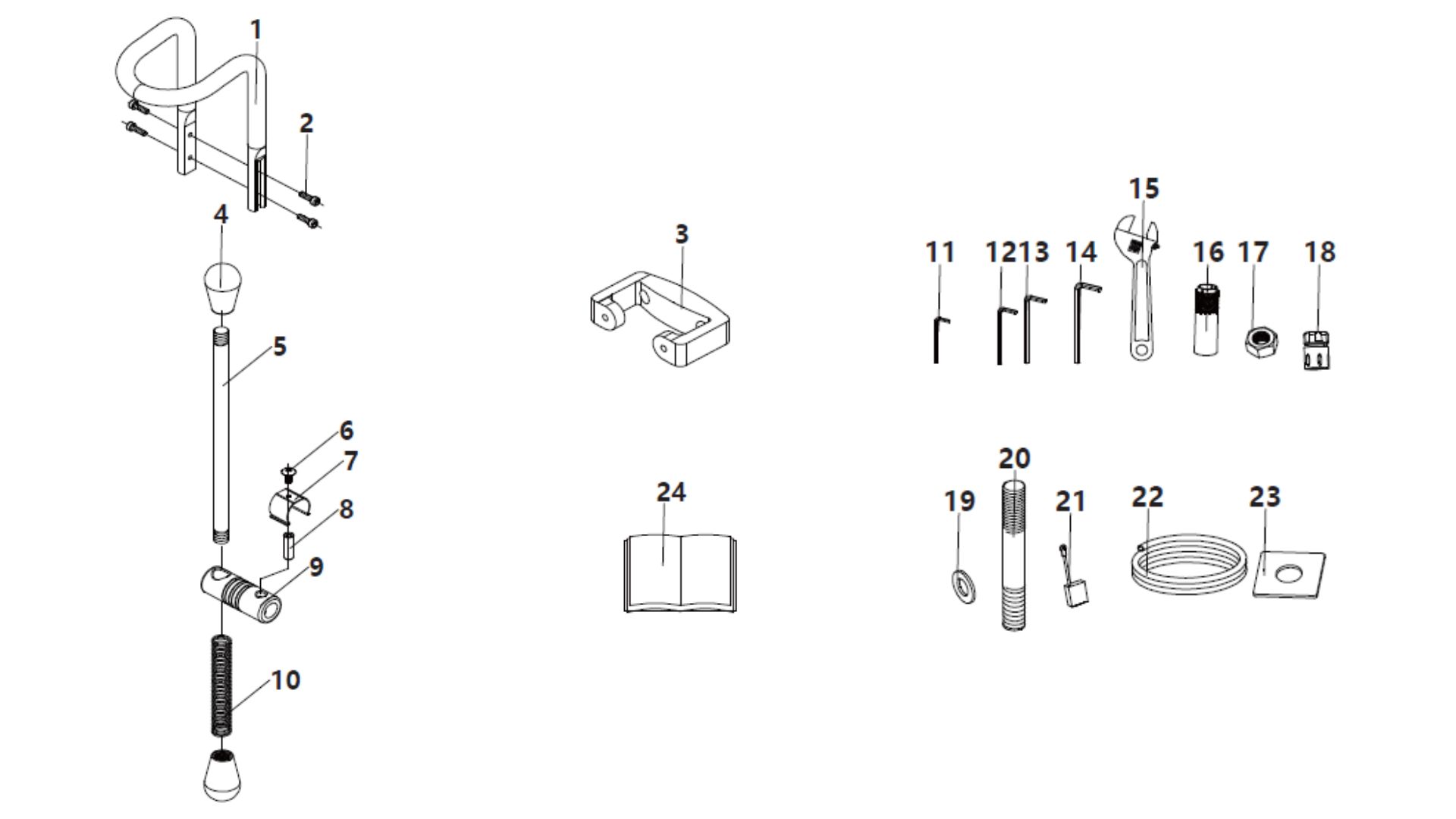
The following items are included with all three models (EDRILC001, EDRILC002, EDRILC003):
- 1 – Handle X1
- 2 – Hexagonal socket screw X4
- 3 – Handle X1
- 4 – Spherical handle X2
- 5 – Feed handle X1
- 6 – Stainless steel flat head screw X1
- 7 – Quickly remove the card X1
- 8 – Fixing pin X1
- 9 – Connecting rod X1
- 10 – Spring X1
- 11 – Wrench X1
- 12 – Wrench X1
- 13 – Wrench X1
- 14 – Wrench X1
- 15 – Adjustable wrench X1
- 16 – Expansion tube X1
- 17 – Nut X1
- 18 – Yellow quick plug connector X1
- 19 – Flat cushion X1
- 20 – Stud X1
- 21 – Carbon brush X1
- 22 – Water pipe X1
- 23 – Square gasket X1
- 24 – Instructions X1
Operating Instructions
Assembly
- When unpacking the carton, you will notice that the base of the drill stand is positioned incorrectly. Remove it using a wrench and reinstall it in the correct direction.
- Measure the distance from the center of the intended cut to the mounting slot location in the base. Follow the concrete anchor manufacturer's instructions for installation. Using a suitable tool (e.g., a rotary hammer), drill the correct sized hole for the anchor. Drive the anchor below flush.
- Move the base into position and insert the anchor bolt, washer, and nut. Leave the nut finger-tight at this stage.
- Using the bubble level (on top of the motor), adjust the four leveling bolts until the stand is level. Once level, fully tighten the center anchor bolt. If precise leveling is required, a carpenter's level may also be used.
WARNING
Never attempt to drill unless the stand is securely fixed.
Drilling Instructions
- Press the "Reset" button on the PRCD interrupter device to energize the machine circuit. Then turn the machine on.
- Open the water valve slightly and begin the cut gently. Apply very light feed pressure to prevent the bit from wandering until it has fully entered the cut.
- Adjust the water feed as required: The exiting water should be a consistent slurry with the appearance of milk.
- If the water is clear → reduce the flow.
- If the water is thick and muddy → increase the flow.
- Once the bit is engaged, apply steady feed pressure for about 30 seconds. Then release feed pressure briefly to allow debris to escape and the bit to cool. Repeat this cycle until the cut is complete.
- When nearing breakthrough, reduce feed pressure. At this stage, the bit is prone to sticking. Grip the machine firmly and proceed carefully.
Mounting the Core Bit
CAUTION
Ensure that the spindle thread and the core bit thread match. Spindle: 1-1/4"-7UNC and G1/2. Mismatched threads will damage both the spindle and the core bit.
Steps:
- Make sure both the core bit and spindle are clean. Debris can cause excessive run-out, which may result in premature bit failure or safety hazards.
- Mount the core bit onto the spindle and tighten using two correct-sized wrenches. Do not use incorrect tools, as this may damage the spindle or bit.
Choosing the Correct Core Bit
Always ensure the core bit is suitable for the material you are drilling.
Maintenance & Service Intervals
CAUTION
Avoid harmful substances: Do not use petrol, diesel, benzene, thinner, alcohol, or similar substances for cleaning. These chemicals can cause discoloration, deformation, or cracks in the tool's materials. Wipe clean as needed. Use mild upholstery cleaner (not caustic) to clean as needed. Never add lubricant to casters!
NOTE
Authorised repairs only: To ensure product safety and reliability, all repairs, maintenance, or adjustments should be performed exclusively by Adendorff Machinery Mart Authorised Service Centres.
Use genuine parts: Always use Adendorff Machinery Mart-approved replacement parts to maintain the tool's performance and warranty coverage.
Storage Instructions
- Keep the tool stored in a dry, level area, away from dampness, moisture, and rainfall.
- Allow the tool to cool down completely before storing.
- Ensure the tool is clean and dry before storage.
- Store the tool in a position where it cannot be accidentally stepped on or moved, especially to reach higher items.
DO NOT:
- Do not store the tool near an ignition source, such as a wood stove, gas or electric heater, or any appliance with a pilot light.
- Do not stack heavy or other items on top of the tool during storage.
IMPORTANT:
- Store the tool out of reach of children or individuals unfamiliar with its operation.
- Avoid direct sunlight or extreme temperatures. Store the tool indoors or in a safe, frost-free area.
Troubleshooting
When troubleshooting electric tools, start by checking the power source – ensure the tool is properly plugged into a functional outlet. Inspect the power switch, fuses, and any reset buttons for signs of malfunction. Look for visible damage to cords, connectors, or terminals, as these can interrupt the power flow. If the tool still doesn't operate, remove any obstructions, clean the contacts, and verify that all safety features or interlocks are properly engaged. Contact Adendorff Machinery Mart Authorised Service Centres to avoid further damage or safety hazards.
| Fault | Reason | Troubleshooting |
|---|---|---|
| Motor does not rotate | The power supply is disconnected or the connector is loose | Restore power, check all connections and tighten |
| Carbon brush stuck, disengaged commutator | Reinstall the carbon brushes | |
| The leakage protector is not reset after it is activated | Press the reset button to restart the motor | |
| The leakage protector is damaged | Replace the leakage protector | |
| Drilling too slow | The drill bit has reached the end of its life | Replace drill bit |
| Feed pressure too low | Increase feed pressure | |
| The drill bit surface is covered with fine chips | Clean the drill bit and increase the water pressure | |
| Speed is too high | Shift to low gear | |
| Cutting the thick steel bar causes slippage | The feeding pressure is reduced, and the pressure is increased after the steel bar is passed | |
| Chip accumulation in machining hole | Clean the bottom of the hole and pressurize | |
| Water flow is not smooth, water leakage or no backflow | Check the water inlet ball valve and water flow | |
| Reduced drill bit sharpness | Resharpen with refractory bricks or grinding wheel | |
| Drilling stuck | Steel bar skin or debris is stuck between the drill core and the drill bit or between the drill bit and the hole wall | Stop the machine and use a wrench to turn the drill bit left or right, or pull out the drill bit to fix the center of the drill |
| Rapid wear of drill hole wall | The rack is not fixed firmly, causing displacement | Re-secure the rack |
| The gap between the rack column and the sliding sleeve is too large | Adjust the sleeve clearance | |
| Spindle misalignment | Repair or replace the spindle | |
| Drill bit is not straight | Replace drill bit | |
| Water jacket leakage | Steel bars or fines cannot be removed from the hole | Improve water flow, remove drill bit, clean hole |
| The machine is turning | The skeleton seal ring is worn or aged | Replace the frame seal |
| Motor clutch is loose | Tighten the clutch |
Disposal Guidelines
When disposing of electric and battery-operated tools, always follow local regulations and environmental guidelines. Start by removing any batteries, as they require separate handling due to their hazardous materials – recycle them at designated battery recycling centres or collection points.
For the tool itself, do not throw it in regular trash; instead, take it to an authorised e-waste recycling facility or a community hazardous waste disposal event.
Always erase any personal data stored in smart tools and ensure components are safely handled to prevent environmental contamination or injury.
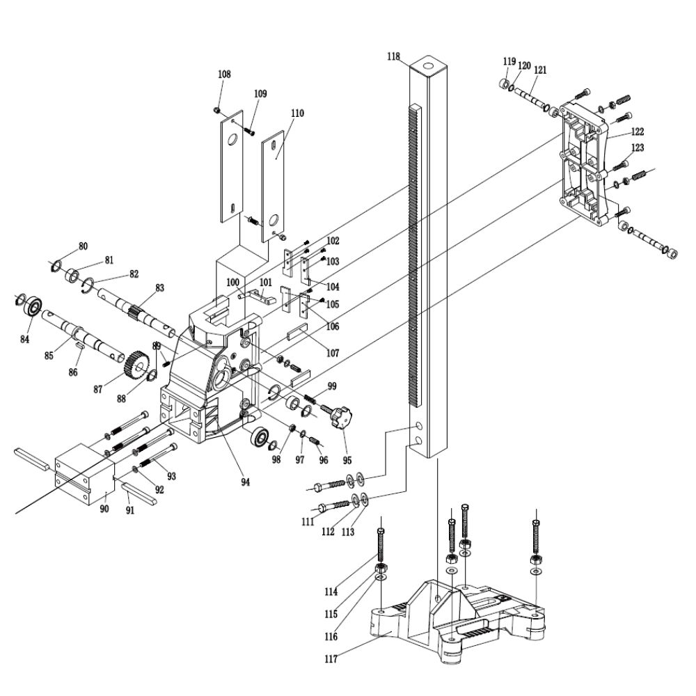
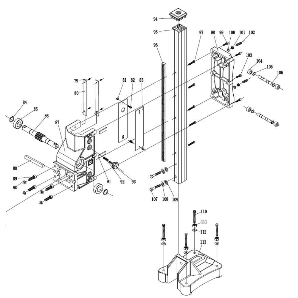
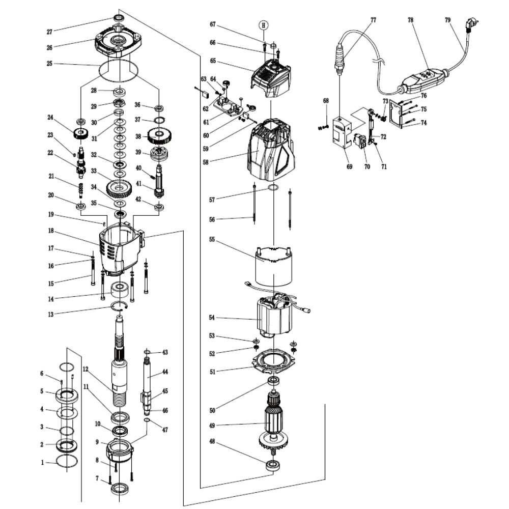
Parts List & Exploded Diagrams
EDRILC001 – Parts List
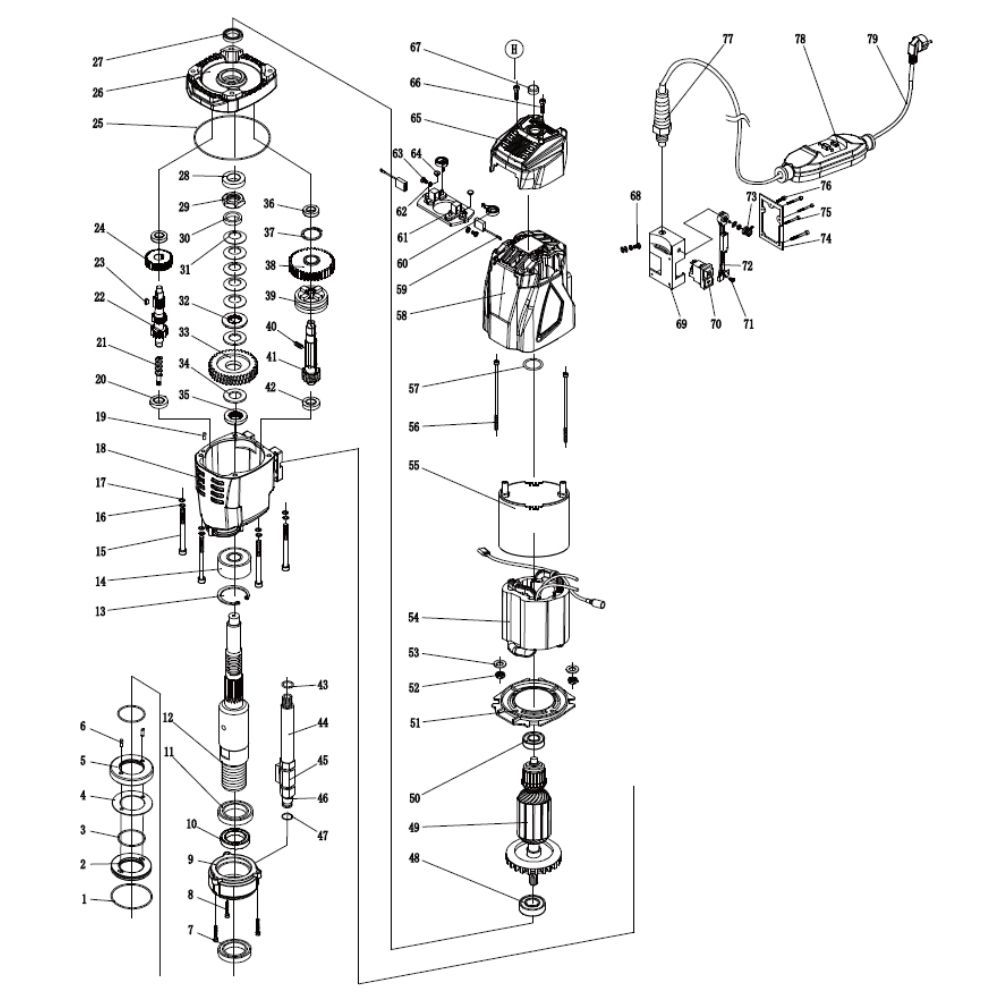
| No. | Name | Quantity | Specifications | Notes |
|---|---|---|---|---|
| 1 | O-ring | 1 | φ52×1.5 | |
| 2 | Equalizer inner ring | 1 | 200A | |
| 3 | O-ring | 4 | φ35×1.5 | |
| 4 | Needle roller gasket | 1 | 32×52×1 | |
| 5 | Balance outer ring | 1 | 200A | |
| 6 | Cylindrical pin | 2 | φ4×12 | |
| 7 | Oil seal | 1 | 40×50×7 | |
| 8 | Hexagonal socket screw | 3 | M5×20 | |
| 9 | Hydrosphere | 1 | 200D | |
| 10 | Oil seal | 1 | 40×50×7 | |
| 11 | Oil seal | 1 | 40×50×7 | |
| 12 | Main shaft | 1 | KF-200-B | |
| 13 | NECKAR | 1 | φ47 | |
| 14 | Bearing | 2 | 6005 LFB | |
| 15 | Hexagonal socket screw | 2 | M6×110 | |
| 16 | Spring washer | 4 | M6 | |
| 17 | Flat cushion | 4 | M6 | |
| 18 | Hexagonal socket screw | 2 | M6×85 | |
| 19 | Gearbox | 1 | 200D | |
| 20 | Cylindrical pin | 1 | φ4×12 | |
| 21 | Bearing | 1 | 6201 LFB | |
| 22 | Threaded column | 1 | 200D | |
| 23 | Grade I gear shaft | 1 | L-200D-2(15) | |
| 24 | Crescent sales | 1 | 4×12 | |
| 25 | Grade I gear | 1 | 200D-1(7) | |
| 26 | O-ring | 1 | φ132×2.2 | |
| 27 | Middle cover | 1 | 200D | |
| 28 | Oil seal | 1 | 15×21×3 | |
| 29 | Muttern | 1 | 250-1 | |
| 30 | Nut | 1 | 200 | |
| 31 | Arc shaped cushion | 2 | 200 | |
| 32 | Spline gasket | 2 | 200-4.0 φ44×4 | |
| 33 | Grade II gear | 1 | 200D-3 | |
| 34 | Clutch plate | 2 | 200 | |
| 35 | Iron ring | 1 | φ16×25×4 200-2 | |
| 36 | Grade II gear shaft | 1 | 200D-4 | |
| 37 | Bearing | 1 | 6201 LFB | |
| 38 | Bearing | 1 | 6201 LFB | |
| 39 | Wild card | 1 | φ22 | |
| 40 | Shaft gear | 1 | 230-5 | |
| 41 | Wild card | 1 | φ24 | |
| 42 | O-ring | 2 | φ15×1.5 | |
| 43 | Hose | 1 | 200A | |
| 44 | Mini ball valve | 1 | 200A | |
| 45 | Faucet connector | 1 | 200A-EU | |
| 46 | O-ring | 1 | φ12×2.5 | |
| 47 | Bearing | 1 | 6202 NSK | |
| 48 | Rotor | 1 | 200D-7(6A) 220V | |
| 49 | Bearing | 1 | 6201 NSK | |
| 50 | Windshield ring | 1 | 200D | |
| 51 | Locknut | 2 | M5 | |
| 52 | Flat cushion | 2 | M5 | |
| 53 | Stator | 1 | 200D(6A) 220V | |
| 54 | Lining | 1 | 200A-I | |
| 55 | Hexagonal socket screw | 2 | M5×105 | |
| 56 | O-ring | 1 | 38×3.1 | |
| 57 | Stator shell | 1 | 200D-H-K | |
| 58 | Carbon brush | 2 | 200A-H | |
| 59 | Coil spring | 2 | 200A | |
| 60 | Brush holder | 1 | 200D-H | |
| 61 | Corrugated gasket | 2 | M4 | |
| 62 | Round head cross screw | 2 | M4×8 | |
| 63 | Hexagonal dust plug | 2 | M5 | |
| 64 | Top cap | 1 | 200D | |
| 65 | Hexagonal socket screw | 2 | M4×10 | |
| 66 | Level | 1 | 18×8 | |
| 67 | Combination screw | 1 | M4×10 | |
| 68 | Switch box | 1 | 200A-FS | |
| 69 | Governor | 1 | SCYRQDGZQ-18A | |
| 70 | Speed control knob | 1 | KN-8D | |
| 71 | Hexagonal socket screw | 4 | M4×50 | |
| 72 | Hexagonal socket screw | 1 | M4×25 | |
| 73 | Anti bending 220V joint | 1 | M16×1.5 | |
| 74 | Leakage protector | 1 | PD22A | |
| 75 | Power line | 1 | 3×1.0×3.5 H07 | |
| 76 | Cross leveling machine screw | 4 | M4×8 | |
| 77 | Small slide | 2 | 200 | |
| 78 | Locknut | 4 | M5 | |
| 79 | Cross leveling machine screw | 4 | M5×20 | |
| 80 | Large slide | 2 | 200 | |
| 81 | Wild card | 2 | 16 | |
| 82 | Bearing | 2 | 6003 | |
| 83 | Elevating axis | 1 | 200 | |
| 84 | Elevator | 1 | 200-CX | |
| 85 | Square pin | 1 | 10×10×95 | |
| 86 | Hexagonal socket screw | 4 | M8×35 | |
| 87 | Flat cushion | 4 | M8 | |
| 88 | Adjust the iron sheet | 2 | 200 | |
| 89 | Spring | 1 | 200-505 12×48×3 | |
| 90 | Plum blossom rubber ball | 1 | M8×30 | |
| 91 | Top cap | 1 | 49×49 | |
| 92 | Aluminum square pole | 1 | 49×49×800 | |
| 93 | Rack | 1 | 14×14×600 (M2) | |
| 94 | Flat head hexagonal screw | 4 | M6×55 | |
| 95 | Cover plate | 1 | 200-CX | |
| 96 | Hexagonal socket screw | 4 | M6×25 | |
| 97 | Flat cushion | 4 | M8 | |
| 98 | Nut | 4 | M8×25 | |
| 99 | Hexagonal socket screw | 2 | M6×35 | |
| 100 | Roller | 4 | 200 | |
| 101 | Wild card | 4 | 10 | |
| 102 | Roller shaft | 2 | 200 | |
| 103 | External hexagon screw | 2 | M12×70 | |
| 104 | Spring washer | 2 | M12 | |
| 105 | Flat cushion | 2 | M12 | |
| 106 | External hexagon screw | 4 | M16×80 | |
| 107 | Nut | 4 | M16 | |
| 108 | Flat cushion | 4 | M16 | |
| 109 | Base | 1 | 200-CX | |
| 110 | Switch | 1 | KJD17B | |
| 111 | Round head cross self tapping screw | 1 | M4×8 | |
| – | Switch box cover | 1 | 200A-FS(TS) | |
| – | Flat head hexagonal tightening screw | 1 | M8 |
EDRILC002 – Parts List
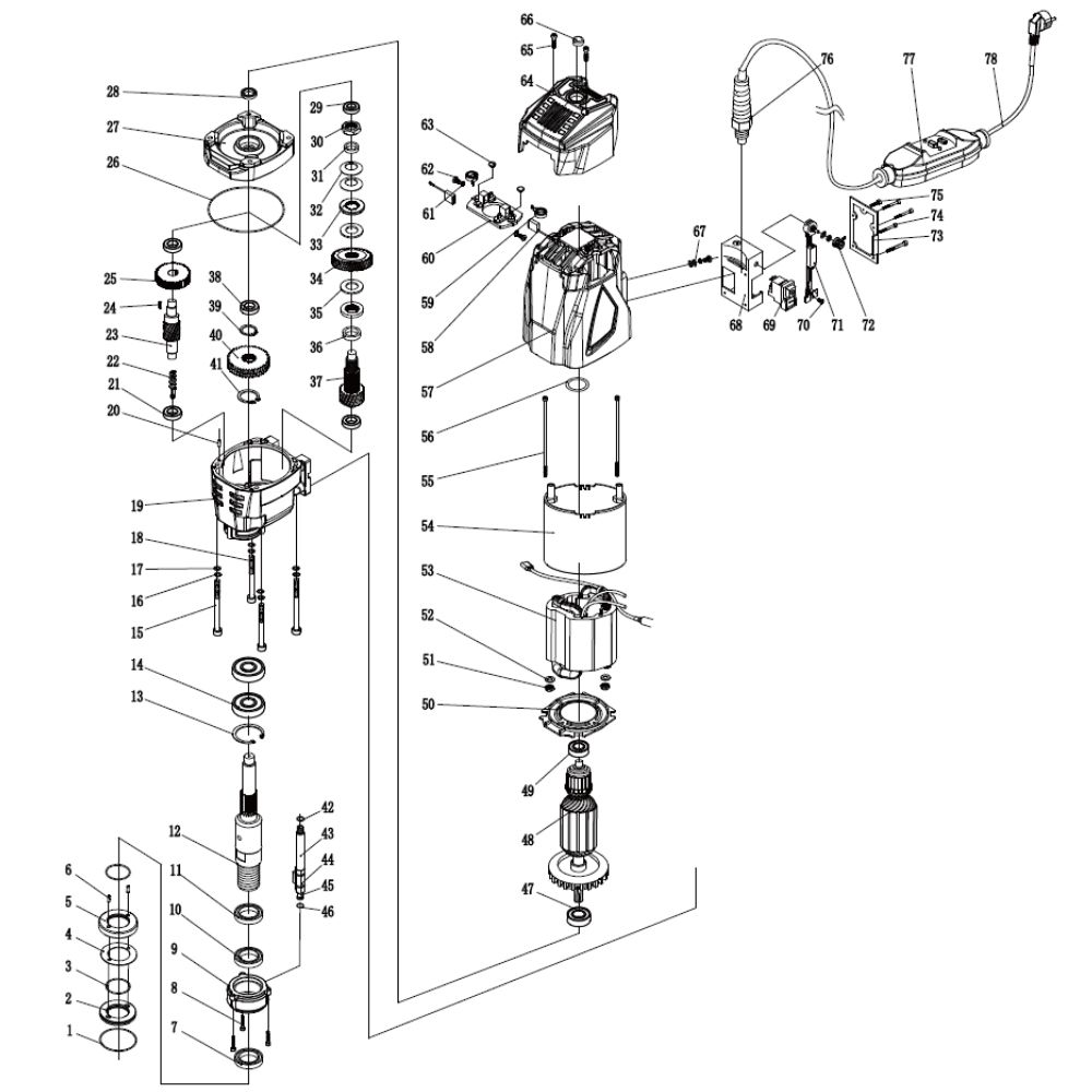
| No. | Name | Quantity | Specifications | Notes |
|---|---|---|---|---|
| 1 | O-ring | 1 | 52×1.5 | |
| 2 | Equalizer inner ring | 1 | 200A | |
| 3 | O-ring | 4 | 35×1.5 | |
| 4 | Needle roller gasket | 1 | 32×52×1 | |
| 5 | Balance outer ring | 1 | 200A | |
| 6 | Cylindrical pin | 2 | φ4×12 | |
| 7 | Oil seal | 1 | 40×50×7 | |
| 8 | Hexagonal socket screw | 3 | M5×20 | |
| 9 | Hydrosphere | 1 | 200D | |
| 10 | Oil seal | 1 | 40×50×7 | |
| 11 | Oil seal | 1 | 40×50×7 | |
| 12 | Main shaft | 1 | KF-200-B | |
| 13 | NECKAR | 1 | φ47 | |
| 14 | Bearing | 2 | 6005 LFB | |
| 15 | Hexagonal socket screw | 2 | M6×110 | |
| 16 | Spring washer | 4 | M6 | |
| 17 | Flat cushion | 4 | M6 | |
| 18 | Hexagonal socket screw | 2 | M6×85 | |
| 19 | Gearbox | 1 | 200D | |
| 20 | Cylindrical pin | 1 | φ4×12 | |
| 21 | Bearing | 2 | 6201 LFB | |
| 22 | Threaded column | 1 | 200D | |
| 23 | Grade I gear shaft | 1 | L-200D-2(13) | |
| 24 | Crescent sales | 1 | 4×12 | |
| 25 | Grade I gear | 1 | 200D-1(7) | |
| 26 | O-ring | 1 | φ132×2.2 | |
| 27 | Middle cover | 1 | 200D | |
| 28 | Oil seal | 1 | 15×21×3 | |
| 29 | Bearing | 1 | 6201 LFB | |
| 30 | Nut | 1 | 200 | |
| 31 | Iron ring | 1 | 200-2 | |
| 32 | Arc shaped cushion | 2 | 200 | |
| 33 | Spline gasket | 2 | 200-4.0 | |
| 34 | Grade II gear | 1 | 230-3 | |
| 35 | Clutch plate | 2 | 200 | |
| 36 | Iron ring | 1 | 250 | |
| 37 | Grade II gear shaft | 1 | 200D-4 | |
| 38 | Bearing | 1 | 6201 LFB | |
| 39 | Wild card | 1 | φ22 | |
| 40 | Shaft gear | 1 | 230-5 | |
| 41 | Wild card | 1 | φ24 | |
| 42 | O-ring | 2 | φ15×1.5 | |
| 43 | Hose | 1 | 200A | |
| 44 | Mini ball valve | 1 | 200A | |
| 45 | Faucet connector | 1 | 200A-EU | |
| 46 | O-ring | 1 | φ12×2.5 | |
| 47 | Bearing | 1 | 6202 NSK | |
| 48 | Rotor | 1 | 200D-7(6A) 220V | |
| 49 | Bearing | 1 | 6201 NSK | |
| 50 | Windshield ring | 1 | 200D | |
| 51 | Locknut | 2 | M5 | |
| 52 | Flat cushion | 2 | M5 | |
| 53 | Stator | 1 | 200D(6A) 220V | |
| 54 | Lining | 1 | 200A-I | |
| 55 | Hexagonal socket screw | 2 | M5×105 | |
| 56 | O-ring | 1 | φ38×3.1 | |
| 57 | Stator shell | 1 | 200D-H-K | |
| 58 | Coil spring | 2 | 200A | |
| 59 | Brush holder | 1 | 200D-H | |
| 60 | Corrugated gasket | 2 | M4 | |
| 61 | Round head cross screw | 2 | M4×8 | |
| 62 | Hexagonal dust plug | 2 | M5 | |
| 63 | Top cap | 1 | 200D | |
| 64 | Hexagonal socket screw | 2 | M4×10 | |
| 65 | Level | 1 | φ18×8 | |
| 66 | Combination screw | 1 | M4×10 | |
| 67 | Switch box | 1 | 200A-FS(TS) | |
| 68 | Switch | 1 | KJD17B | |
| 69 | Round head cross self tapping | 1 | M4×8 | |
| 70 | Governor | 1 | SCYRQDGZQ-18A | |
| 71 | Knob | 1 | KN-8D | |
| 72 | Switch box cover | 1 | 200A-FS(TS) | |
| 73 | Hexagonal socket screw | 4 | M4×50 | |
| 74 | Hexagonal socket screw | 1 | M4×25 | |
| 75 | Anti bending joint | 1 | M16×1.5 | |
| 76 | Leakage protector | 1 | PD22A | |
| 77 | Power line | 1 | 3×1.5×3.5 220V | |
| 78 | Cross leveling machine screw | 4 | M4×8 | |
| 79 | Small slide | 2 | 200 | |
| 80 | Locknut | 4 | M5 | |
| 81 | Cross leveling machine screw | 4 | M5×20 | |
| 82 | Large slide | 2 | 200 | |
| 83 | Wild card | 2 | φ16 | |
| 84 | Bearing | 2 | 6003 | |
| 85 | Elevating axis | 1 | 200 | |
| 86 | Elevator | 1 | 200-CX | |
| 87 | Square pin | 1 | 10×10×95 | |
| 88 | Hexagonal socket screw | 4 | M8×35 | |
| 89 | Flat cushion | 4 | M8 | |
| 90 | Adjust the iron sheet | 2 | 300 | |
| 91 | Spring | 1 | 200-505 10×76 | |
| 92 | Plum blossom rubber ball | 1 | M8×30 | |
| 93 | Top cap | 1 | 49×49 | |
| 94 | Aluminum square pole | 1 | 49×49×900 | |
| 95 | Rack | 1 | 14×14×700 (M2) | |
| 96 | Flat head hexagonal screw | 5 | M6×55 | |
| 97 | Cover plate | 1 | 200-CX | |
| 98 | Hexagonal socket screw | 4 | M6×25 | |
| 99 | Flat cushion | 4 | M8 | |
| 100 | Nut | 4 | M8×25 | |
| 101 | Flat head hexagonal tightening | 4 | M8 | |
| 102 | Hexagonal socket screw | 2 | M6×35 | |
| 103 | Roller | 4 | 200 | |
| 104 | Wild card | 4 | φ10 | |
| 105 | Roller shaft | 2 | 200 | |
| 106 | External hexagon screw | 2 | M12×70 | |
| 107 | Spring washer | 2 | M12 | |
| 108 | Flat cushion | 2 | M12 | |
| 109 | External hexagon screw | 4 | M16×80 | |
| 110 | Nut | 4 | M16 | |
| 111 | Flat cushion | 4 | M16 | |
| 112 | Base | 1 | 200-CX |
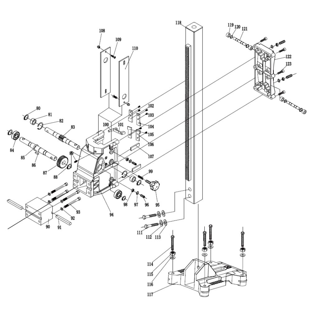
EDRILC003 – Parts List
| No. | Name | Quantity | Specifications | Notes |
|---|---|---|---|---|
| 1 | O-ring | 1 | φ52×1.5 | |
| 2 | Equalizer inner ring | 1 | 200A | |
| 3 | O-ring | 2 | φ35×1.5 | |
| 4 | Needle roller gasket | 1 | 32×52×1 | |
| 5 | Balance outer ring | 1 | 200A | |
| 6 | Cylindrical pin | 2 | φ4×12 | |
| 7 | Oil seal | 1 | 40×50×7 | |
| 8 | Hexagonal socket screw | 3 | M5×20 | |
| 9 | Hydrosphere | 1 | 200D | |
| 10 | Oil seal | 1 | 40×50×7 | |
| 11 | Oil seal | 1 | 40×55×7 | |
| 12 | Main shaft | 1 | – | |
| 13 | NECKAR | 1 | – | |
| 14 | Bearing | 1 | – LFB | |
| 15 | Hexagonal socket screw | 4 | M6×130 | |
| 16 | Spring washer | 4 | M6 | |
| 17 | Flat cushion | 4 | M6 | |
| 18 | Gearbox | 1 | 250D | |
| 19 | Cylindrical pin | 1 | φ4×12 | |
| 20 | Bearing | 2 | 6201 LFB | |
| 21 | Threaded column | 1 | 200D | |
| 22 | Grade I gear shaft | 1 | L-200A/3-2 | |
| 23 | Grade I gear | 1 | LFB | |
| 24 | O-ring | 1 | φ132×2.2 | |
| 25 | Middle cover | 1 | 250D | |
| 26 | Oil seal | 1 | 15×21×3 | |
| 27 | Bearing | 1 | 6202 LFB | |
| 28 | Nut | 1 | 200A | |
| 29 | Iron ring | 1 | 200A-800 | |
| 30 | Arc shaped cushion | 1 | 200A | |
| 31 | Spline gasket | 5 | 250A-5.0 | |
| 32 | Clutch plate | 1 | – | |
| 33 | Bearing | 1 | 3205 | |
| 34 | Square pin | 1 | 4×10 | |
| 35 | Shaft gear | 1 | 250A-1(6) | |
| 36 | Spline gasket | 1 | 250A-B φ52 | |
| 37 | Reverse axis with external | 1 | – | |
| 38 | Grade II low-speed gear | 1 | 250A/2-7(80) | |
| 39 | Grade II sliding gear | 1 | 250A-11 | |
| 40 | Grade II gear shaft | 1 | – | |
| 41 | Ball head plunger | 1 | M8×15 | |
| 42 | Bearing | 1 | 6202 LFB | |
| 43 | O-ring | 2 | 15×1.5 | |
| 44 | Hose | 1 | 200A | |
| 45 | Mini ball valve | 1 | 200A | |
| 46 | Faucet connector | 1 | 200A-EU | |
| 47 | O-ring | 1 | φ12×2.5 | |
| 48 | Bearing | 1 | 6202 LFB | |
| 49 | Rotor | 1 | 200D-6(6A) 220V | |
| 50 | Bearing | 1 | 6201 LFB | |
| 51 | Windshield ring | 1 | 200D | |
| 52 | Locknut | 2 | M5 | |
| 53 | Flat cushion | 3 | M5 | |
| 54 | Stator | 1 | 200D(6A) 220V | |
| 55 | Lining | 1 | 200A-I | |
| 56 | O-ring | 2 | M5×105 | |
| 57 | Stator shell | 1 | φ38×3.1 | |
| 58 | Coil spring | 1 | 200D-H-K | |
| 59 | Brush holder | 2 | 200A | |
| 60 | Corrugated gasket | 1 | 200D-H | |
| 61 | Round head cross screw | 2 | M4 | |
| 62 | Hexagonal dust plug | 2 | M4×8 | |
| 63 | Top cap | 2 | M5 | |
| 64 | Hexagonal socket screw | 1 | 200D | |
| 65 | Level | 2 | M4×10 | |
| 66 | Combination screw | 1 | φ18×8 | |
| 67 | Switch box | 1 | M4×10 | |
| 68 | Switch | 1 | 200A-FS(TS) | |
| 69 | Round head cross self tapping | 1 | KJD17B | |
| 70 | Governor | 1 | M4×8 | |
| 71 | Knob | 1 | SCYRQDGZQ-18A | |
| 72 | Switch box cover | 1 | KN-8D | |
| 73 | Hexagonal socket screw | 4 | 200A-FS(TS) | |
| 74 | Hexagonal socket screw | 4 | M4×50 | |
| 75 | Anti bending joint | 1 | M4×25 | |
| 76 | Leakage protector | 1 | M16×1.5 | |
| 77 | Power line | 1 | PD22A | |
| 78 | Bearing | 1 | 3×2×4.0 220V | |
| 79 | Elevating axis | 4 | φ16 | |
| 80 | Square pin | 2 | 250 | |
| 81 | Flat cushion | 1 | 250-2 | |
| 82 | Hexagonal socket screw | 2 | 6003 | |
| 83 | Wild card | 1 | 250-1 | |
| 84 | JDB | 1 | 6×18 | |
| 85 | Elevating axis | 1 | 250 | |
| 86 | Lifting gear | 1 | φ18 | |
| 87 | Wild card | 1 | 100×70×100 | |
| 88 | Aluminum block | 2 | 10×10×95 | |
| 89 | Square pin | 4 | M8 | |
| 90 | Hexagonal socket screw | 4 | M8×135 | |
| 91 | Plum blossom rubber ball | 1 | M8×30 | |
| 92 | Flat head hexagonal tightening screw | 4 | M8×25 | |
| 93 | Shim | 4 | M8 | |
| 94 | Nut | 4 | M8 | |
| 95 | Spring | 1 | 200-505 12×55×3 | |
| 96 | Adjust the iron sheet | 2 | 300 | |
| 97 | Locknut | 4 | M5 | |
| 98 | Cross leveling machine screw | 4 | M5×18 | |
| 99 | Large slide | 2 | 200 | |
| 100 | External hexagon screw | 2 | M14×80 | |
| 101 | Spring washer | 2 | M14 | |
| 102 | Flat cushion | 2 | M14 | |
| 103 | External hexagon screw | 4 | M14×80 | |
| 104 | Nut | 4 | M14 | |
| 105 | Flat cushion | 4 | M14 | |
| 106 | Base | 1 | 300Z | |
| 107 | Iron square pole | 1 | 59×59×1000 | |
| 108 | Roller | 4 | 200 | |
| 109 | Wild card | 4 | φ10 | |
| 110 | Roller shaft | 2 | 200 | |
| 111 | Cover plate | 1 | 250 | |
| 112 | Hexagonal socket screw | 6 | M6×25 |
Customer Support – Repairs & Warranty
Warranty Period
This product is warranted for 12 months from the date of purchase by the first user.
Coverage
The warranty covers all material or production flaws, with exceptions:
- Batteries and chargers
- Parts subject to normal wear (e.g., bearings, brushes, cables, plugs)
- Accessories (e.g., drill bits, saw blades)
Exclusions
The warranty does not cover damage or defects from:
- Maltreatment, accidents, or alterations
- Inappropriate or negligent use of the tool
- Overloading, fluid permeation, excessive dust, or intentional damage
- Non-compliance with manual instructions, inexpert assembly, lightning, or incorrect voltage
Liability
Adendorff Machinery Mart disclaims liability for bodily injury resulting from improper tool use.
Repairs
All warranty repairs must be conducted by an authorised Adendorff Machinery Mart repair centre. All stores have in-house service technicians.
Transportation Costs
Transportation costs for service are the customer's responsibility unless otherwise agreed in writing.
Warranty Claims
- All warranty claims do not extend or restart the warranty period.
- Claims may be rejected if purchase cannot be verified or if product maintenance is found to be lacking.
- A 3-month (Three Months) warranty applies to any repairs performed.
Maintenance and Proof of Purchase
- Maintain the product as instructed (e.g., clean ventilation slots, service carbon brushes regularly).
- Retain the purchase receipt as proof of purchase date.
Return Conditions
Return the product intact, in clean condition, and in its original blow-moulded case (if applicable), along with proof of purchase.
How to Claim
- Locate your nearest branch: Visit our website at www.adendorff.co.za and use the Store Locator to find the nearest branch to you.
- Prepare product details: Before contacting or visiting a branch, please have the following information ready:
- Product name and model number
- Proof of purchase (invoice or receipt)
- A brief description of the issue or fault
- Contact or visit the branch: Phone: Call your nearest Adendorff Machinery Mart branch directly for repair intake or service queries. In Person: Bring the product to the branch for assessment. Ensure it is clean and safely packed for transport.
- Warranty repairs: If your item is still under warranty, repairs will be handled according to the warranty terms. Ensure you bring the original receipt with the product.
- Out-of-warranty repairs: For items no longer under warranty, a quotation will be provided for approval before any work begins.
Note
Repairs may take several business days depending on parts availability and workshop load. You will be contacted once your item is ready for collection.
Need Help?
For full warranty details, visit www.adendorff.co.za. For assistance, contact the national call centre at 011 434 7000.
DANGER! Read all safety regulations and instructions.
Keep all safety regulations and instructions in a safe place for future use.
Supplied by:
Adendorff Machinery Mart
98 Sailor Malan Avenue, Aeroton, Johannesburg, 2190
www.adendorff.co.za
Made in P.R.C.