5TON Four Post Platform Lift (GLIFTS004): Operation Manual Guide
5TON Four Post Platform Lift (GLIFTS004): Original Operating Instructions
Welcome to the Adendorff family! We're delighted to have you with us and thank you for choosing our product. Your trust and support are greatly appreciated, and we are confident that this device will serve you well.
Please read this manual carefully before installation and use. It contains important safety information and operating instructions that must be followed to ensure proper and safe operation. Keep this manual for future reference.
Taking the time to familiarise yourself with the product will help you maximise its performance and ensure a smooth, trouble-free experience.
If you have any questions or require assistance, please don't hesitate to contact our support team.
Appendix: This section is for reference by professional installers only; ordinary users do not need to read it.
Table of Contents
Product Introduction
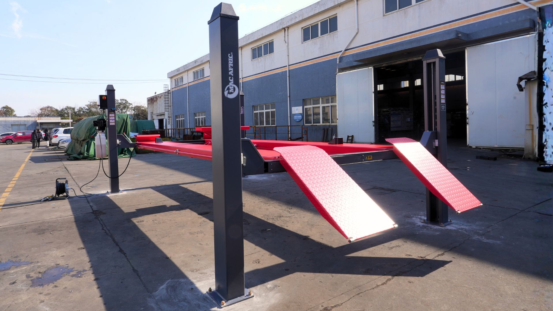
The 5 Ton Four Post Platform Lift (Model GLIFTS004) is a stationary hydraulic vehicle lifting system designed for use in professional workshops, service centres, and automotive maintenance facilities.
This lift is intended solely for lifting and supporting complete motor vehicles within its rated capacity of 5 tonnes, to allow safe access for inspection, servicing, maintenance, and repair operations. The four-post design provides stable, level lifting for a wide range of passenger vehicles and light commercial vehicles.
The lift is designed for indoor installation on a reinforced concrete floor and must be installed, operated, and maintained in accordance with the instructions contained in this manual. Operation is restricted to trained and authorised personnel only.
Intended Use
- Raising and lowering complete motor vehicles
- Supporting vehicles at working height during maintenance or inspection
- Use in controlled workshop environments
Prohibited Use
This product must not be used for:
- Lifting or supporting persons
- Lifting individual vehicle components or loose loads
- Exceeding the rated lifting capacity
- Outdoor operation or installation
- Use on unsuitable surfaces or unstable foundations
Any use outside of the intended purpose is considered misuse and may result in serious injury, equipment damage, or warranty invalidation. Adendorff Machinery Mart accepts no liability for damage or injury resulting from improper or unauthorised use.
Specification
1. Technical Parameter – 5TON Platform Four Post Lift
| Type | Lifting Capacity | Lifting/Lowering Time | Lifting Height | Total Height | Total Width | Total Length |
|---|---|---|---|---|---|---|
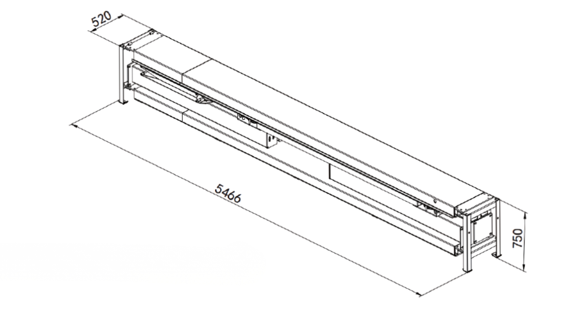
| GLIFTS004 | 5TON | <75s | 1750mm | 2205mm | 3480.5mm | 5494mm |
2.5TON Rolling Jack (Optional)
Not included — needs to be purchased separately from Adendorff Machinery Mart.
| Lifting Capacity | UP/DOWN Time | Lifting Height | Total Width | Total Length |
|---|---|---|---|---|
| 2500kg | <25s | 488mm | 430mm | 1130mm |
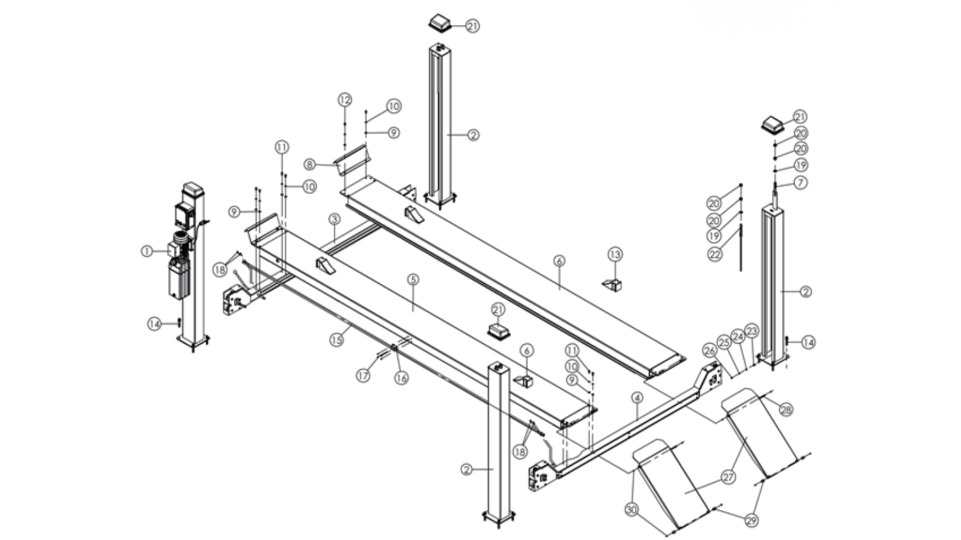
2. The Main Structure of the Whole Machine
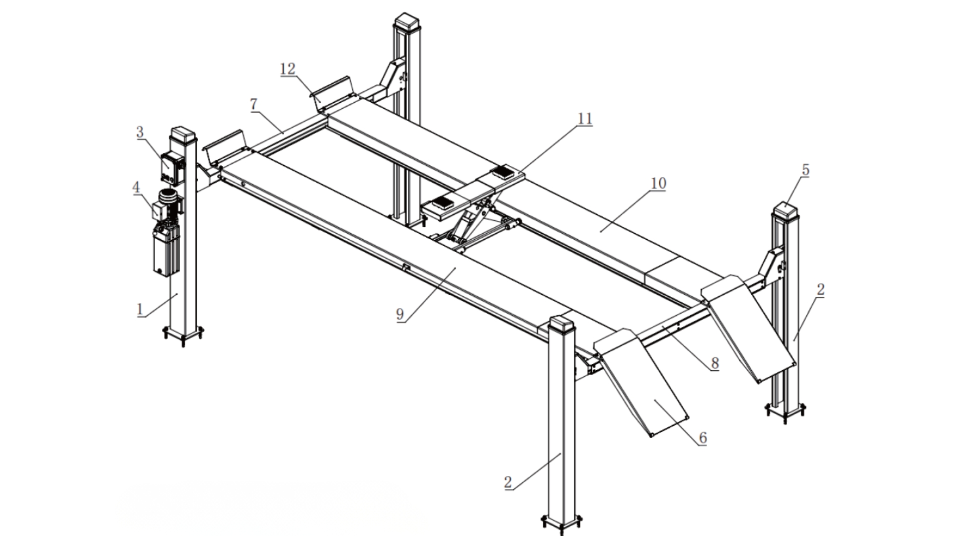
1) Main column
2) Auxiliary column
3) Control box
4) Power unit
5) Column cap
6) Ramp
7) Main crossbeam
8) Auxiliary crossbeam
9) Main platform
10) Auxiliary platform
11) Rolling jack (Optional)
12) Wheel stop plate
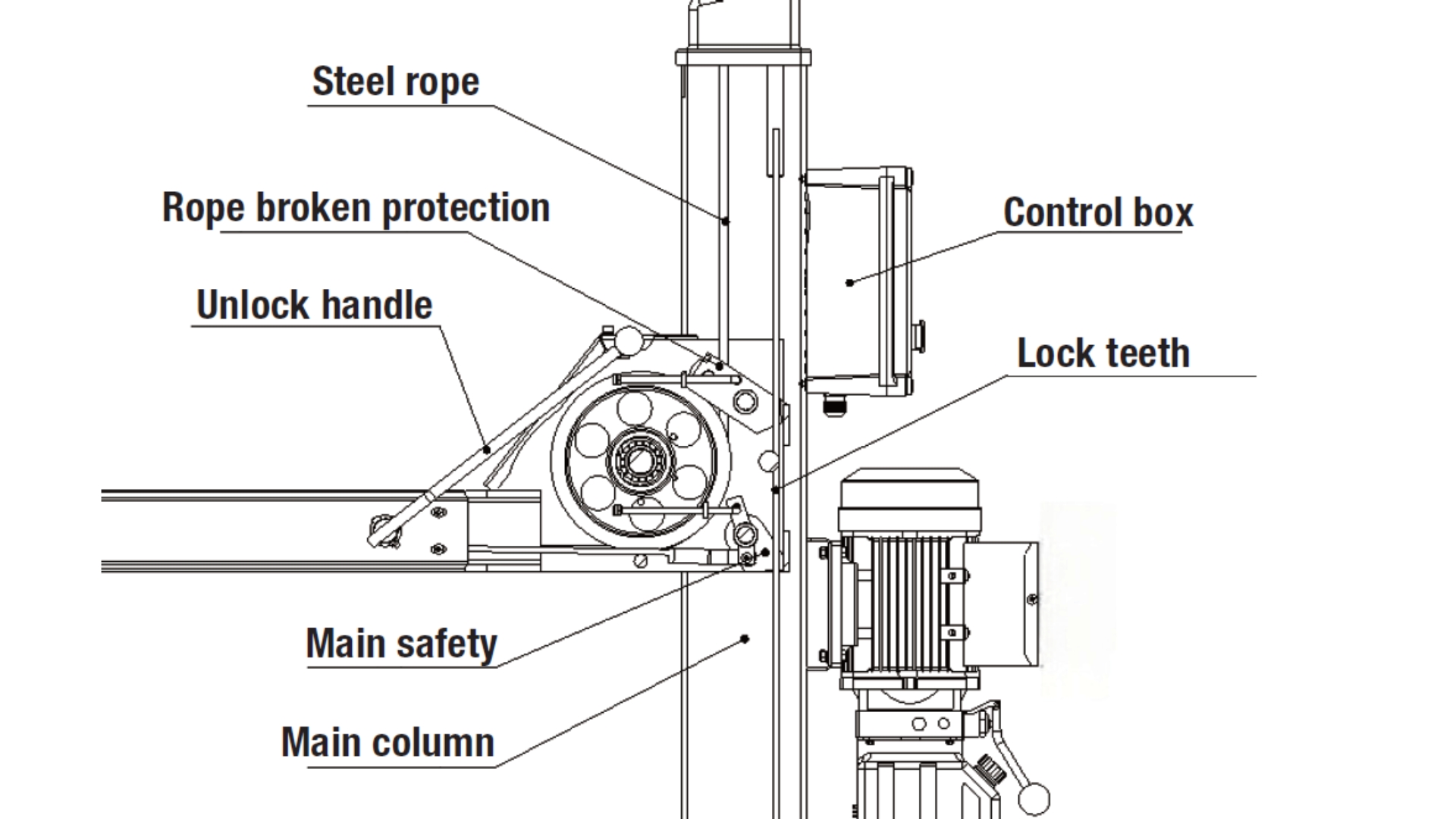
3. Safety Structure Icon
Safety Warnings
1. Important Statement
- The lifting machine is designed exclusively for lifting vehicles. Any other use is prohibited. Neither the dealers nor the company are liable for accidents or damage resulting from unauthorized uses.
- Be sure to pay attention to the tonnage mark on the machine and do not attempt to lift vehicles exceeding the rated capacity.
- Please read the manual carefully before installation and operation to avoid potential property damage or personal injury.
- Users may not alter the control or other mechanical parts without the manufacturer's explicit permission.
2. Qualified Operator and Instructions
- Professional, trained personnel may operate the lift.
- Electrical connections must be handled by qualified personnel.
- Non-professionals should not operate lifting machines.
3. Instructions of Consideration
- Do not install the lift on asphalt. The concrete thickness must meet specified requirements.
- Before operation, carefully read and understand the safety instructions.
- Lifts are generally not intended for outdoor use and are not typically customized for special customer needs.
- Keep hands and feet away from moving parts. When the machine is lowering, ensure hands and feet are removed to avoid injury.
- The operator is not permitted to wear loose clothing that could be caught in moving parts during operation.
- The lifting machine must be kept clean and tidy and should not be cluttered to prevent accidents.
- The lift is designed to lift vehicles as a whole, not individual parts. Do not attempt to lift vehicles exceeding the rated capacity.
- When working under a vehicle, ensure the safety lock is engaged.
- Inspect components for damage at any time, check the synchronization of the machine and the flexibility of moving parts, pay attention to regular maintenance, and stop using the machine immediately and contact the dealer if any abnormality is found.
- Lower the machine to its minimum position after operation.
- Do not modify the lift components without the permission of the manufacturer.
- If the machine is not to be used for a long period of time, the user shall:
- A. Disconnect the power supply
- B. Drain the hydraulic oil
- C. Lubricate the moving components with grease
Installation Overview
ATTENTION!
The car lift is a high-risk product. Improper installation, operation, or unauthorized modification of mechanical parts may cause injury or death. Carefully read the manual, strictly follow requirements, and avoid random liquid discharge to protect the environment.
All safety warning signs on the machine are designed to alert operators to dangerous situations. Keep them clean and replace them if detached or damaged. Read and memorize their meanings.
Lifting machine noise should be below 75dB for health safety. It is recommended to place a noise meter in your work area and monitor the machine's noise at any time.
Important
Installation must be carried out by qualified technicians in accordance with local building, electrical, and safety regulations. Improper installation may result in serious injury or equipment damage.
Step 1 – Site Preparation
- Verify indoor installation location
- Confirm reinforced concrete floor:
- Minimum thickness: 300 mm
- Level tolerance: ≤ 5 mm
- Ensure sufficient clearance around the lift for operation and maintenance
- Confirm power supply availability (230 V / 50 Hz / single-phase)
Step 2 – Unpacking & Component Verification
- Unpack all lift components using suitable lifting equipment
- Verify contents against the Package Contents / Packing List
- Inspect all components for transport damage
- Do not proceed if parts are missing or damaged
Step 3 – Positioning & Layout
- Mark column positions according to the foundation layout drawing
- Confirm diagonal measurements are equal to ensure squareness
- Position columns, platforms, and crossbeams loosely in place
- Ensure all columns are vertical and parallel before anchoring
Step 4 – Mechanical Assembly
- Assemble platforms, crossbeams, ramps, and safety components
- Route and connect steel cables and pulleys as supplied
- Install safety ladders and locking mechanisms
- Do not fully tighten fasteners until alignment is verified
(Detailed diagrams are provided in the Assembly Drawings section)
Step 5 – Hydraulic System Connection
- Connect hydraulic hoses between power unit and cylinder
- Ensure all fittings are clean and securely tightened
- Fill hydraulic tank with approved anti-wear hydraulic oil:
- ISO VG 32 (below 18 °C)
- ISO VG 46 (above 18 °C)
Step 6 – Electrical Connection
CAUTION!
Electrical work must be performed by a qualified electrician.
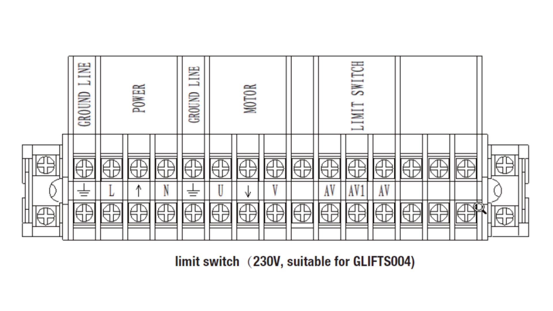
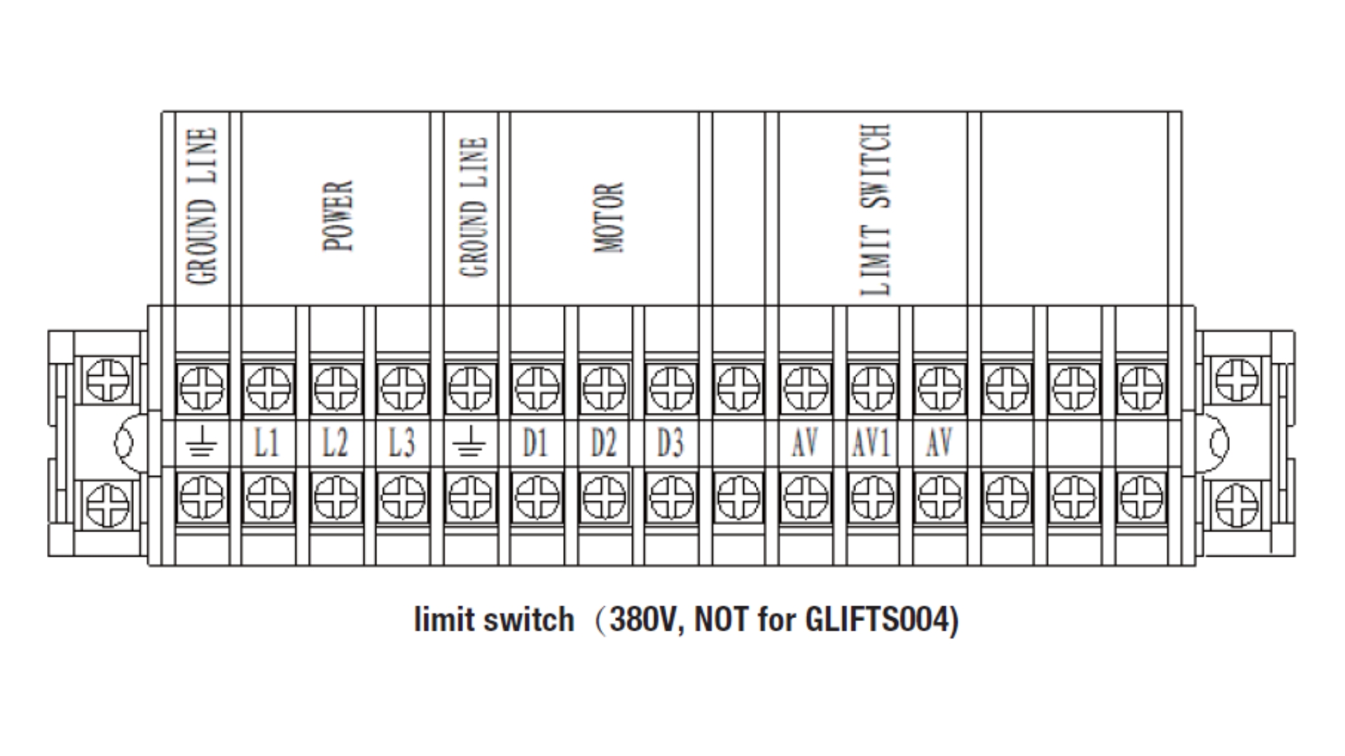
- Connect power supply according to wiring diagram
- Verify correct voltage and phase
- Test emergency stop and limit switch functionality
Step 7 – Anchoring to Floor
- Drill anchor holes through column base plates
- Install expansion anchor bolts
- Shim base plates as required to achieve vertical alignment
- Torque anchors securely once alignment is confirmed
Step 8 – Synchronisation & Adjustment
- Perform initial lift without a vehicle
- Adjust steel cables to level platforms
- Set and verify safety lock engagement at all columns
- Ensure smooth, level lifting and lowering operation
Step 9 – Final Safety Inspection
Before first use, confirm:
- All fasteners are fully tightened
- Safety locks engage correctly
- Hydraulic system shows no leaks
- Electrical controls function correctly
- Lift operates smoothly without abnormal noise
Step 10 – Commissioning
- Perform test lift with no load
- Perform test lift with a suitable vehicle within rated capacity
- Hand over lift for operational use
Operating Instructions
Important General Safety Notice
- This equipment may only be operated by trained and authorised personnel.
- The operator must remain at the controls at all times while the lift is moving.
- Never allow any person to stand beneath a vehicle while the lift is raising or lowering.
- Always ensure safety locking mechanisms are engaged before working under a raised vehicle.
A. Four-Post Lift – Operating Instructions (Primary Equipment)
A1. Pre-Operation Checks (Before Each Use)
Before operating the four-post lift, verify the following:
- The lift is securely anchored and level
- No visible damage to steel cables, hydraulic hoses, or safety locks
- Safety locking mechanisms engage correctly
- Control box, emergency stop, and limit switches function correctly
- The lift area is clear of tools, obstructions, and bystanders
- Do not operate the lift if any abnormality is detected.
A2. Positioning the Vehicle
- Drive the vehicle slowly onto the platforms.
- Ensure the vehicle is centred lengthwise and laterally on the lift.
- Apply the vehicle handbrake and switch off the engine.
- Install wheel stop plates where applicable.
CAUTION!
Incorrect vehicle positioning may cause instability or damage.
A3. Raising the Lift
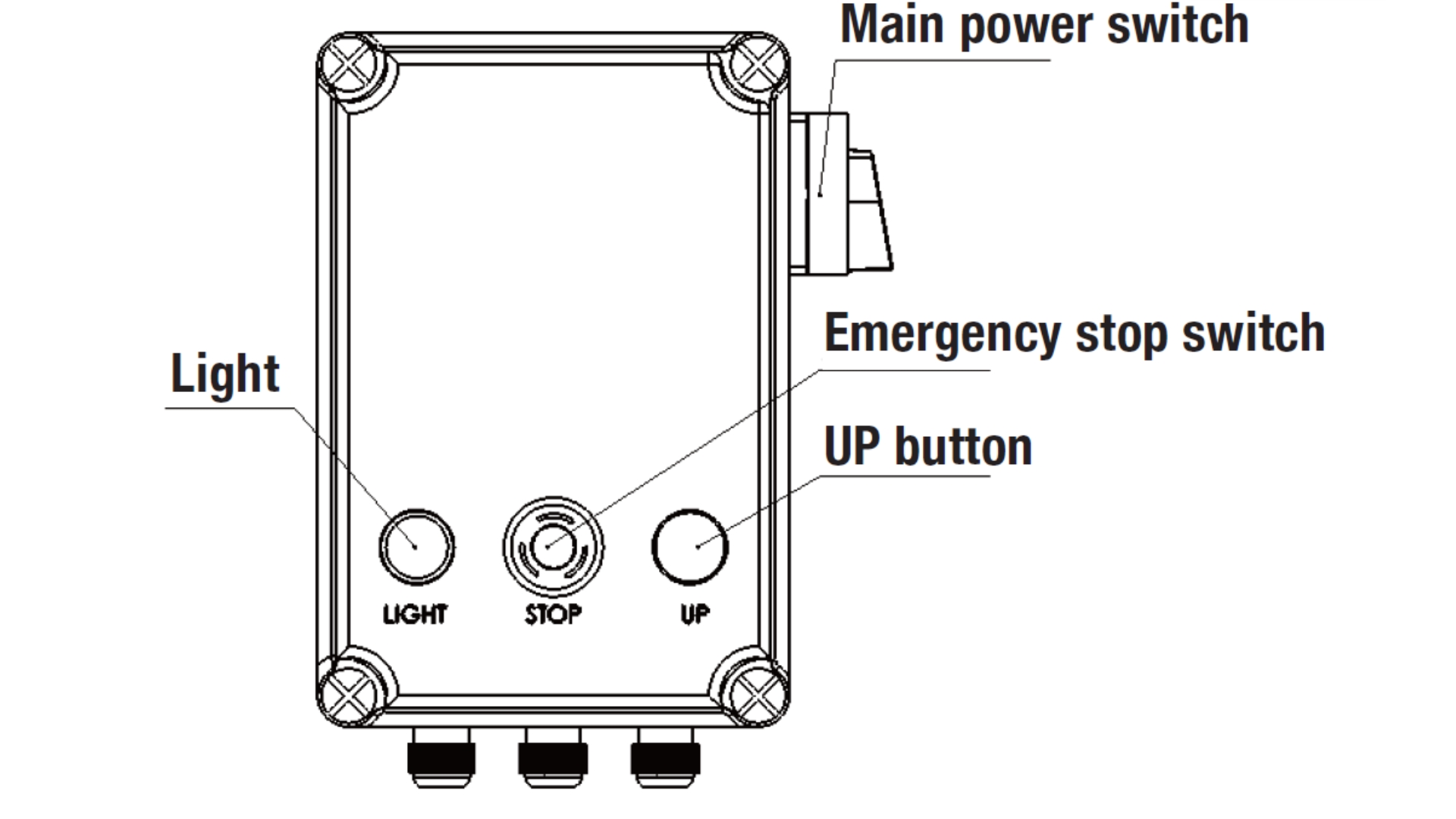
- Turn on the main power supply.
- Release the emergency stop button.
- Press the UP button to raise the lift.
- Observe the lift during ascent and listen for abnormal noise.
- Release the button once the desired height is reached.
A4. Engaging the Safety Locks
- Slightly lower the lift until the safety locks engage fully.
- Confirm all four safety locks are seated evenly.
- Switch off the power before commencing work under the vehicle.
CAUTION!
Do not leave the controls while the lift is moving.
A5. Lowering the Lift
- Ensure the area beneath the lift is completely clear.
- Switch on the power supply.
- Press the UP button briefly (30–50 mm) to release the safety locks.
- Operate the unlocking lever and lowering control simultaneously.
- Lower the lift smoothly to its lowest position.
- Once fully lowered, remove wheel stop plates and drive the vehicle away.
A6. Emergency Stop & Abnormal Operation
- Press the Emergency Stop immediately if abnormal noise, vibration, or instability occurs.
- Do not resume operation until the issue has been inspected and resolved by qualified personnel.
Control Box Operation
B. Optional Rolling Jack – Operating Instructions (Accessory)
Important
The rolling jack is an optional accessory and not supplied as standard. The following instructions apply only if the rolling jack is installed.
The rolling jack must never be used as the primary lifting device.
B1. Purpose of the Rolling Jack
The rolling jack is designed to raise vehicle axles or wheels after the vehicle has already been lifted and securely supported by the four-post lift.
B2. Pre-Operation Checks
- Ensure the four-post lift safety locks are fully engaged
- Verify the rolling jack is correctly positioned on the platform rails
- Confirm air or hydraulic supply connections (depending on jack type)
- Ensure no persons are beneath the vehicle
B3. Raising the Rolling Jack
- Position the rolling jack beneath the designated lifting point.
- Press the PUMP / UP control to raise the jack.
- Raise only to the required height.
- Engage the rolling jack safety lock where provided.
B4. Lowering the Rolling Jack
- Ensure the area beneath the vehicle is clear.
- Release the rolling jack safety lock.
- Operate the release / unloading valve to lower the jack slowly.
- Confirm the jack is fully lowered before repositioning or removing it.
B5. Important Safety Notes (Rolling Jack)
- Never exceed the rolling jack's rated capacity
- Do not move the rolling jack while under load
- Do not work under a vehicle supported only by the rolling jack
C. Shutdown After Use
- Lower the lift completely
- Switch off the power supply
- Clean the operating area
- Store the rolling jack (if fitted) in its designated position
D. Operator Responsibility Statement
Failure to follow these operating instructions may result in injury, equipment damage, or warranty invalidation. Adendorff Machinery Mart accepts no liability for damage or injury resulting from improper operation or unauthorised use.
Troubleshooting
Note
If you can't solve the problem, please contact the manufacturer for help. We will help you solve the problem for the first time, and provide the relevant fault information and the trouble picture to enable the manufacturer to troubleshoot you at the fastest speed.
| Fault Phenomenon | Cause | Solution |
|---|---|---|
| Abnormal sound | The cylinder's inside whether or not friction marks | Add lubricating oil to the inner column |
| The cylinder is whether or not obstacles | Clean up internal obstacles | |
| The motor does not turn and not rise | The motor cut off the wire | Replace the motor |
| Bad wire contact | Check and connect the lines | |
| The limit switch is off line. The action is bad. | Connect the line. Adjust or replace the limit switch | |
| Motor reversal | Correct wire connection | |
| The motor turns but does not rise | Overflow valve looseness or obstacles | Adjust or clean the overflow valve |
| The gear pump is damaged | Replace the gear pump | |
| Hydraulic oil insufficiency | Replenishing hydraulic oil | |
| The suction pipe is loose | Tightening suction pipe | |
| Cushion valve looseness or obstacles | Tighten or clean the buffer valve | |
| Oil cylinder seal is poor | Replacement of seals | |
| Slow rise | The one-way valve is poor | Decomposition of cleaning to rule out or replace |
| Improper overflow valve | Decomposition of cleaning to rule out or replace | |
| The manual unload valve or the electromagnet unloading valve is not good | Decomposition of cleaning to rule out or replace | |
| Whether the steel cable is loose and not adjusted | Check whether the wire rope is levelled | |
| The oil filter is blocked | Decomposition of cleaning to rule out or replace | |
| After the rise, slowly unloading | Oil pressure mixed with air | Replenishing hydraulic oil |
| The overflow valve adjustment is not in place | Adjust | |
| The hydraulic oil heats up (more than 45°) | Replace the hydraulic oil | |
| Wear of oil cylinder seals | Replacement of seals piece | |
| Slow down | Cylinder lubrication is not good | Replace the lubricating oil in the cylinder |
| The throttle valve is stuck and there are obstacles | Decomposition of cleaning to rule out or replace | |
| The hydraulic oil is dirty | Replace the hydraulic oil | |
| Slow down (continued) | The Explosion-proof throttle valve has obstruction | Replace explosion-proof throttle valve |
| Slow down (continued) | Oil tube obstruction | Oil tube obstruction |
| A wire rope has a rough edge | No butter lubrication during installation | Replace the steel cable |
Maintenance
The routine maintenance of simple and low cost can ensure the normal operation and safety of the machine. The following are the routine maintenance requirements.
The following recommended routine maintenance time can be based on the use environment and frequency of the lift.
The parts that need lubrication are shown below:
- A: The wire rope needs lubrication.
- B: The sliding blocks inside and outside the column need lubrication.
- C: All pulley shafts need lubrication.
- D: The main safety device needs lubrication.
- E: The broken rope safety device needs lubrication.
1. Check the Following Items Before Daily Operation
The operator must undergo an inspection before the operation machine, and the inspection of the safety lock is very important and must be checked every day to guard against the failure to ensure that you will not suffer serious loss. It doesn't waste time, it doesn't kill people.
- At the time of operation, according to the sound judgment, the locking of the safety lock.
- Check the connection and leakage of the hydraulic pipe.
- Check the connection of the chain, the connection of the steel cable, the electrical part.
- Check the fastening of anchor bolts.
- Check the lock tooth situation of arm lock.
2. Weekly Check Content
- Check the flexibility of the moving parts.
- Check the status of security components.
- Check the volume of hydraulic oil. Press the ascending key to make the platform rise to the highest level. If you can't reach the highest altitude, the hydraulic oil in the tank is not enough.
- Check the tightening of expansion bolts.
3. Contents of Monthly Routine Inspection
- Fastening of bolts
- The sealing of hydraulic system, if oil leak detection, tighten the joint position.
- Check the shaft pin, roller, carriage structure, lubrication and wear of lifting arm and related parts. The damage will be changed in time.
- Check the lubrication and wear of the steel cable.
4. Content of Annual Routine Inspection
- Empty the tank to check the hydraulic oil condition.
- Clean the filter in the tank.
Note
The car lift must be used with "lithium base grease" lubrication.
Warranty Terms & Conditions
Warranty Period
12 months from purchase date (first user only).
Coverage
Manufacturing and material defects.
Excludes: batteries, chargers, wear parts (bearings, brushes, cables, plugs), accessories (drills, drill bits, saw blades).
Exclusions
- Misuse, maltreatment, accidents, or modifications.
- Overloading, fluid ingress, excessive dust, or intentional damage.
- Failure to follow instructions or use correct voltage.
Liability
Adendorff Machinery Mart accepts no liability for injuries caused by improper use.
Repairs
Warranty repairs must be carried out at authorised Adendorff repair centres. A 3-month warranty applies to all repairs.
Transport Costs
Transport is the customer's responsibility unless agreed in writing.
Claims
Warranty claims require proof of purchase. Claims do not extend or reset the warranty period.
Returns
Return product intact, clean, and in original case (if applicable). Include proof of purchase.
Contact
For full warranty details, visit www.adendorff.co.za or call 011 434 7000.
Appendix A: Detailed Installation & Assembly Guide
Appendix Note
This section is for reference by professional installers only; ordinary users do not need to read it.
1. Before Installation
1) Tools and Equipment Needed
- Lifting equipment – 1 piece
- #20 Anti-wear hydraulic oil – 12L
- Electric hammer drill
- Chalk
- Tape measure
- Magnetic plumb line
- Ф15mm horizontal pipe – 8 m
- Open spanner – 1 set
- Inner hexagon spanner – 1 set
- A cross screwdriver
- A flathead screwdriver
- A needle nose pliers
- Ф17, Ф19, Ф22 Socket wrench – each 1 pcs
- Hammer – 1 pcs (4 pounds)
- Circlip pliers – 1 pcs
2) Ground Requirement
The car lift must be installed on a level concrete surface with a minimum thickness of 300mm and a concrete strength exceeding 3000 psi (the leveling tolerance must be less than 5mm). For newly poured concrete, a curing period of at least 20 days is required before installation.
3) Check Accessories
Upon opening the package, verify all components against the complete machine packing list in Enclosure 1. Immediately report any missing parts to the distributor or manufacturer.
2. Precautions During Installation
- Ensure both upright columns remain parallel to each other and perfectly vertical to the ground during installation. Any tilting must be avoided.
- All hydraulic hose and steel cable connections must be securely fastened in place to prevent potential oil leakage and cable loosening.
- Verify that all bolts and nuts are properly tightened to ensure full fastening integrity.
- Strictly prohibit any vehicle placement on the lift during test operations.
3. Installation Steps
Step 1: Choose a Suitable Location
The lifting platform is for indoor installation only. Install it on solid concrete, not on expansion joints in cement floors. Do not install it on the ground floor of a second-floor or higher building without permission from relevant building personnel.
Step 2
Once the installation location is determined, the lift will be moved to the installation site by lifting equipment.
Step 3
Move the power unit around.
Step 4
Move the rolling jack around.
Step 5: Unpacking
- First place wooden strips (higher than 120mm) on the ground. Use lifting equipment to place the whole packing frame on the wooden strips, so that the bottom of the packaging frame is off the ground.
- Remove the packaging material.
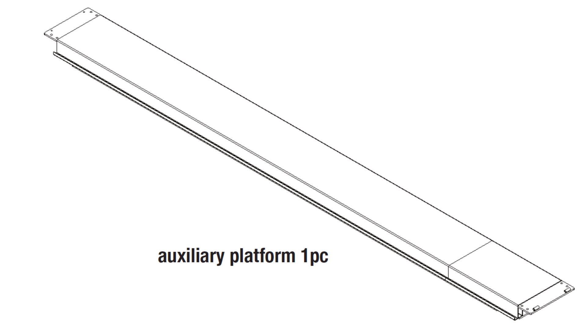
- Remove the connecting screws between the upper platform (auxiliary platform) and the steel frame. Use lifting equipment to lift this platform down and place it in an open area.
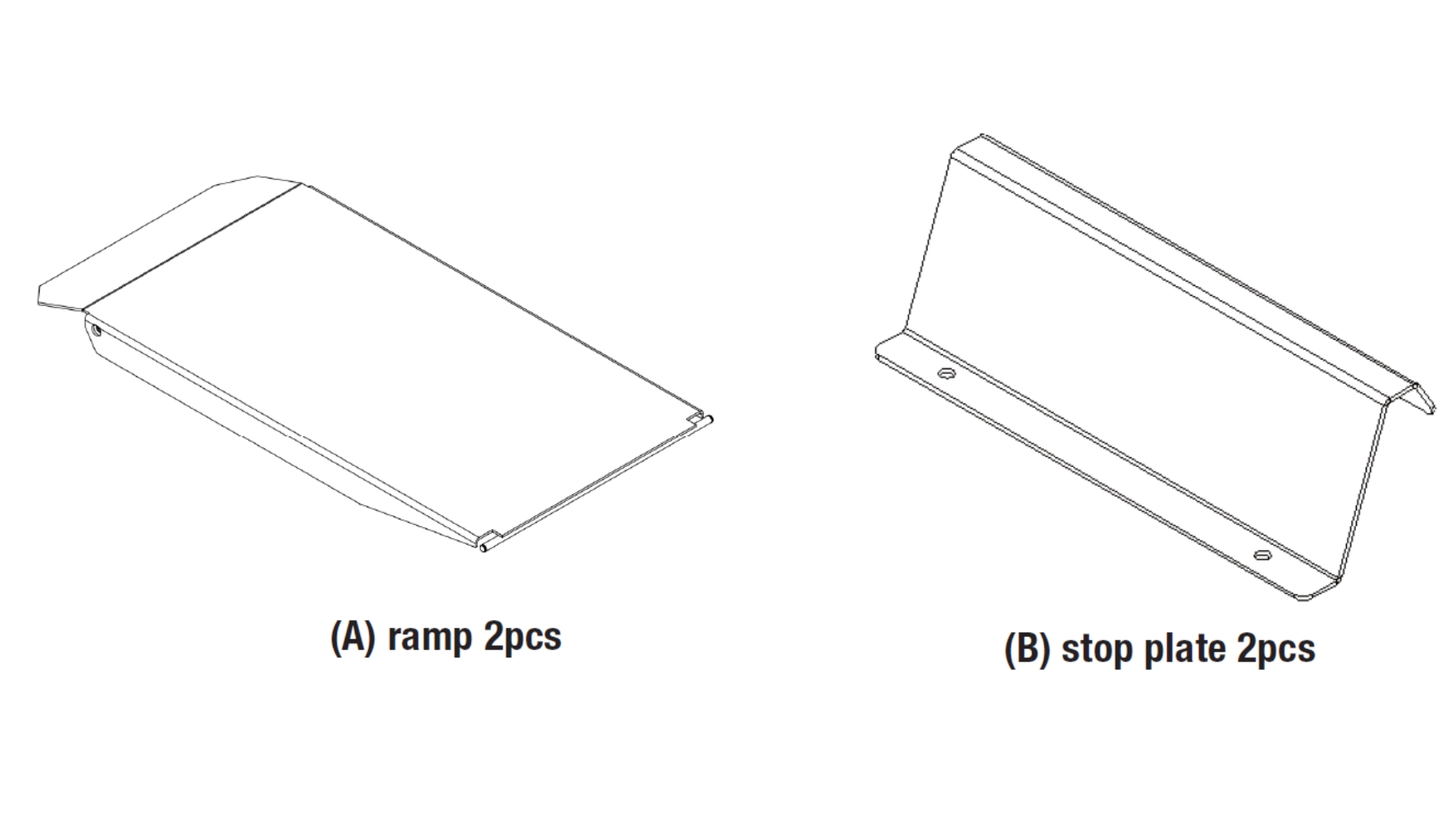
- Remove the packing straps, take out A: ramp 2pcs, B: stop plate 2pcs, and C: accessory box 1pcs, and then put them in an open area.
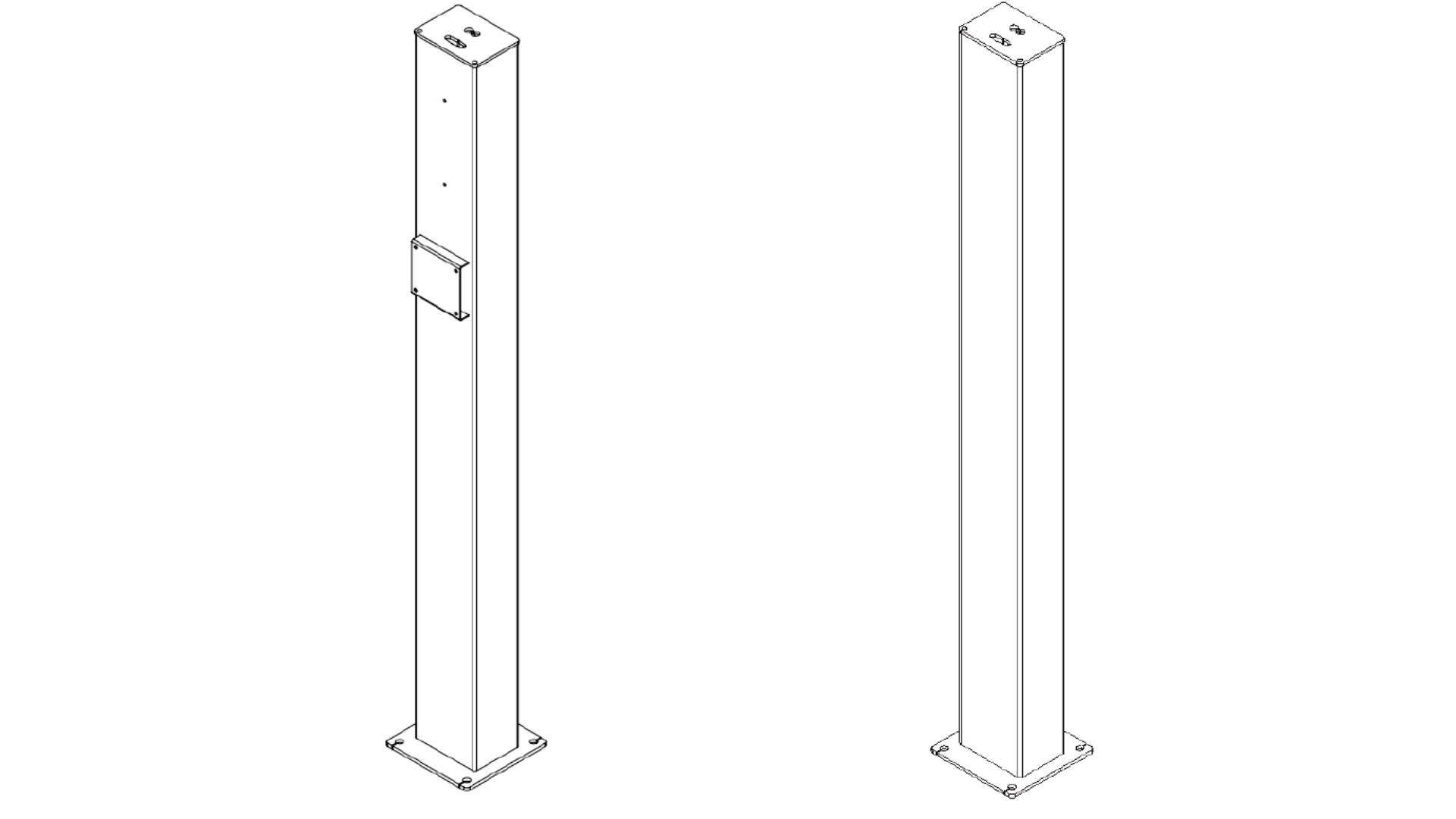
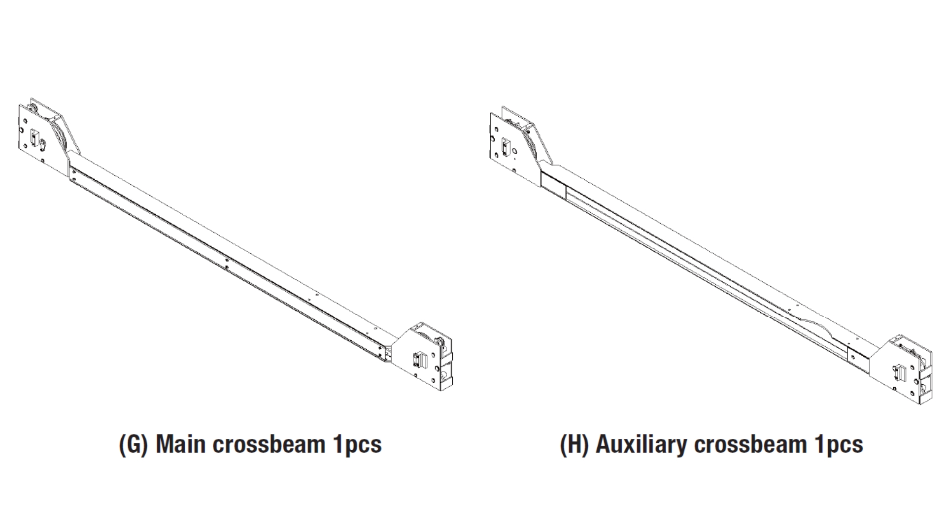
- Remove the packing straps and connecting screws, take out E: main column 1pcs, F: auxiliary column 3pcs, G: main crossbeam 1pcs, and H: auxiliary crossbeam 1pcs in an open area.
- Remove the connecting screws between the bottom platform (main platform) and the steel frame. Remove the steel frame, use the lifting equipment and lift the platform to an open area.
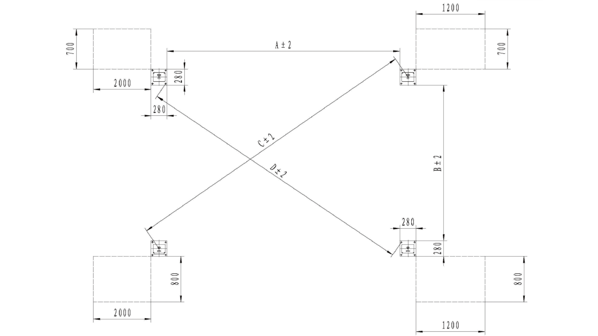
Step 6: Determine the Machine Installation Layout
Mark the standing points of the four columns using a measuring tape and chalk, ensuring that the two diagonals are the same length.
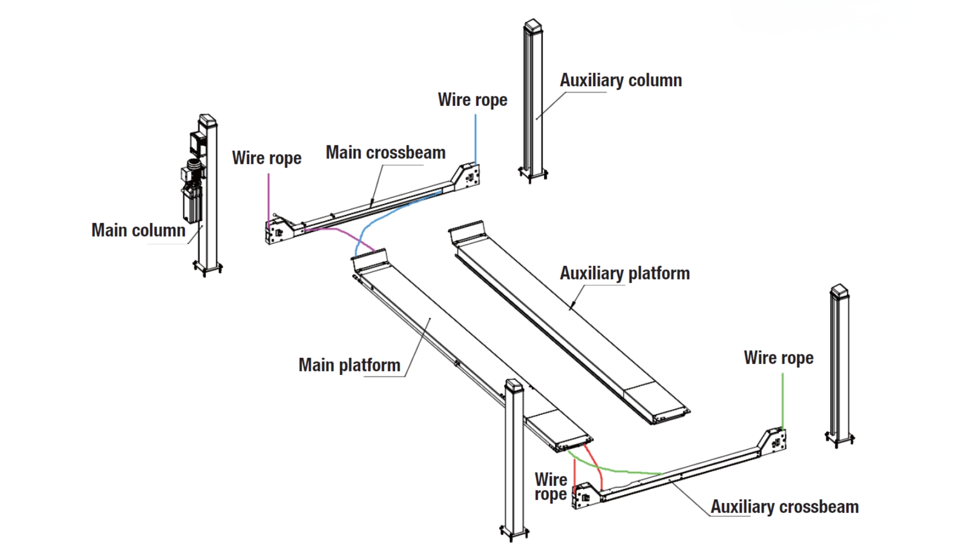
Step 7: Positioning the Major Components
Use lifting equipment to position the major components of the lift as shown in the diagram below:
- For ease of installation, please put the crossbeam on the tire rubber blocks.
- Pull the wire rope out of the main platform and thread it into the pulleys of the main and auxiliary crossbeams.
A: The main and auxiliary platforms are pre-installed at the factory, including the connection of the hydraulic cylinders, wire ropes, and hydraulic hoses.
B: The main and auxiliary crossbeams are pre-installed at the factory, including the connection of the unlocking device, the main safety device, the broken rope safety device, and the rope pulleys.
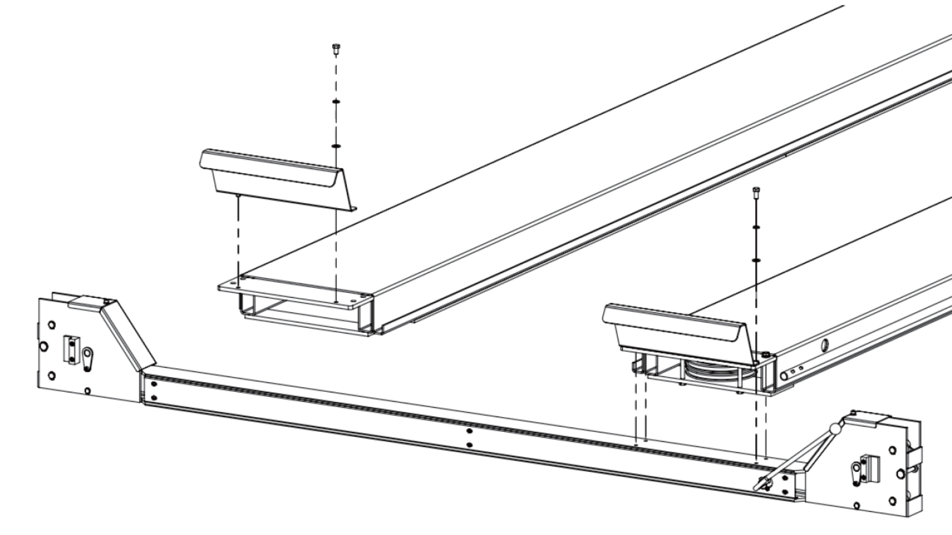
Step 8: Connect the Crossbeams to the Platforms
Connect the main and auxiliary crossbeams to the main and auxiliary platforms, and assemble the stop plate onto the main and auxiliary platforms, as shown in the figure below:
- Connect the main and auxiliary crossbeams to the main platform with M12*25 hex bolts, flat washers, and spring washers.
- Assemble the stop plates onto the main and auxiliary platforms with M12*16 hex bolts, flat washers, and spring washers.
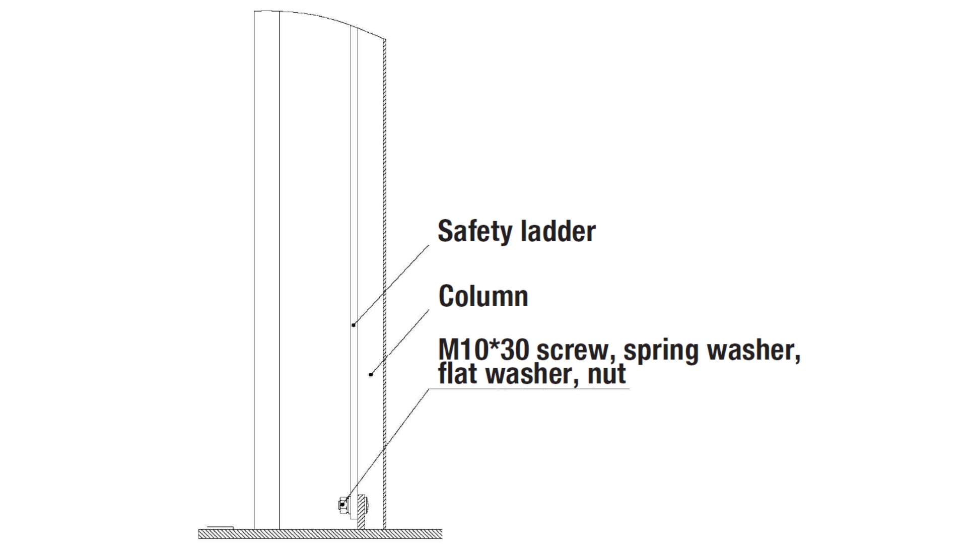
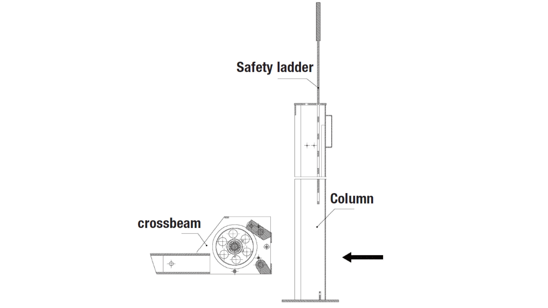
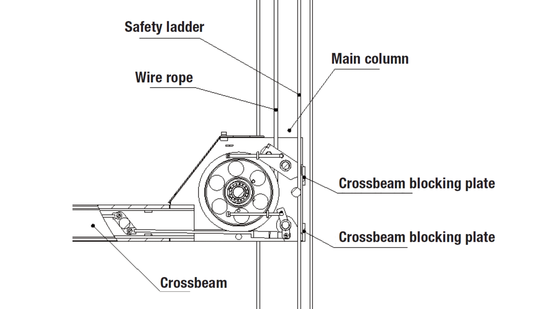
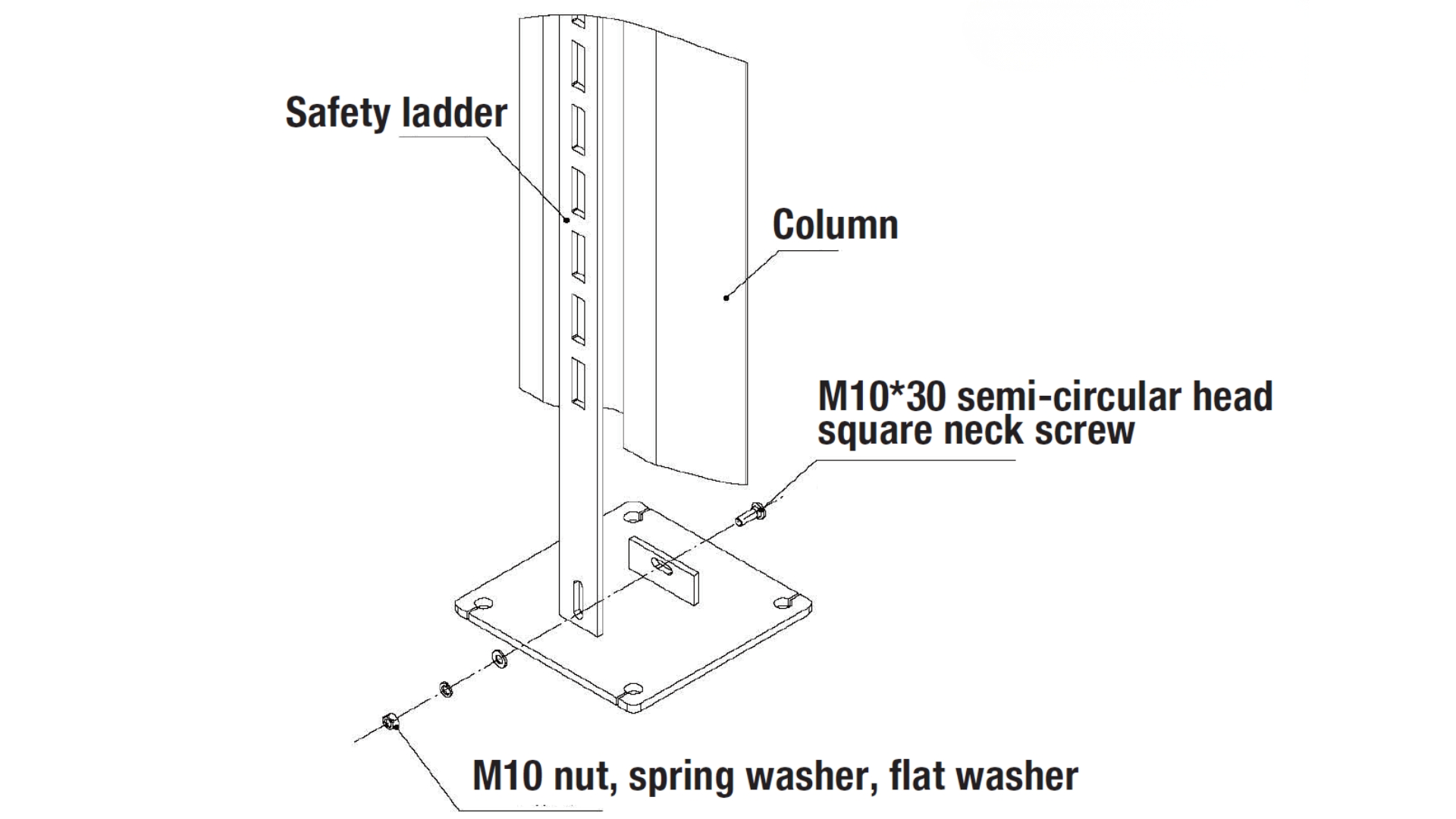
Step 9: Assemble the Crossbeam onto the Column
- Remove the M10*30 semi-circular head square neck screw, M10 spring washer, M10 flat washer, and M10 nut to allow the safety ladder to be movable.
- Raise the safety ladder inside the column (higher than the crossbeam), as shown in the diagram below, and push the column into the crossbeam in the direction of the arrow.
- Insert the safety ladder into the crossbeam by the inner side of the crossbeam blocking plates.
- Secure the bottom of the safety ladder with a M10*30 semi-circular head square neck screw, spring washer, flat washer, and nut.
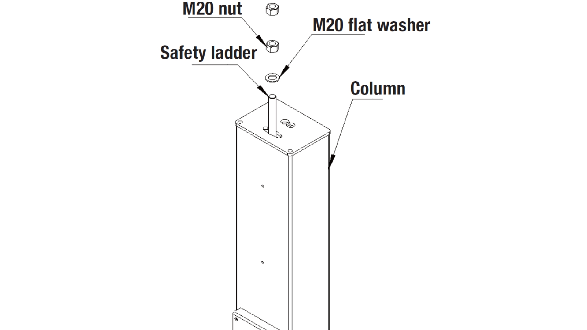
- Secure the safety ladder to the top of the column with a M20 flat washer and nut.
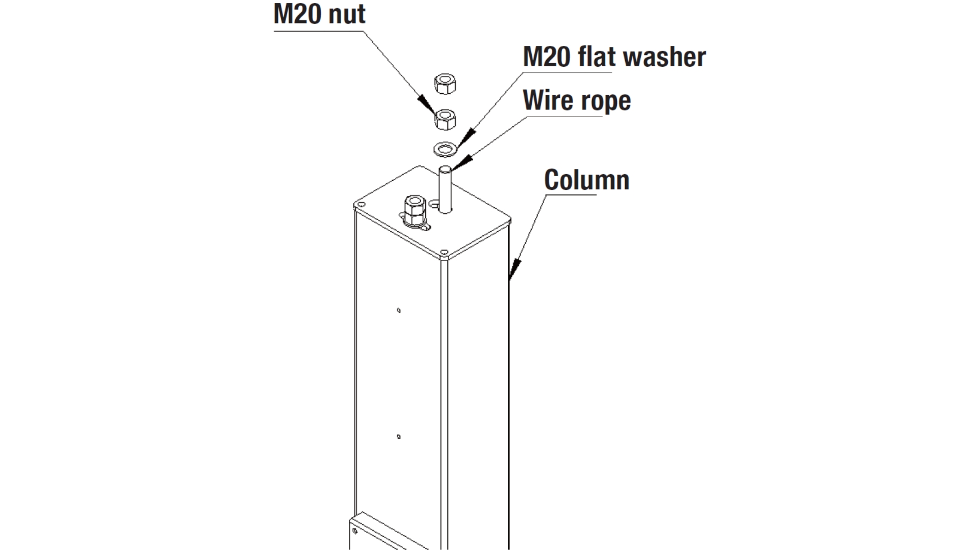
- Pull out the wire ropes at both ends of the crossbeam and connect them to the top plate of the column, and secure them with M20 nuts and flat washers.
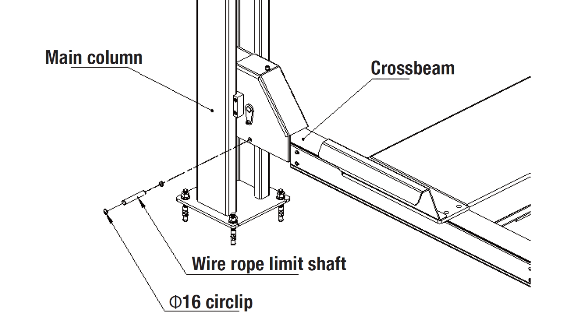
Step 10: Assemble the Wire Rope Limit Shaft
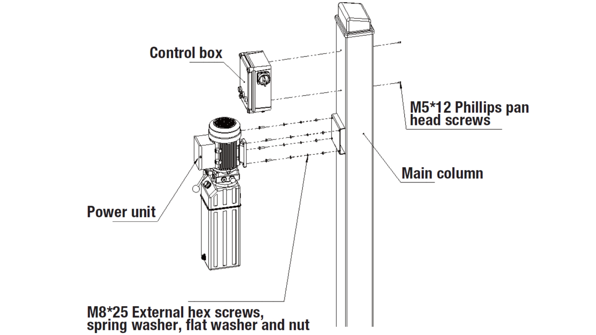
Step 11: Assemble the Power Unit and Control Box
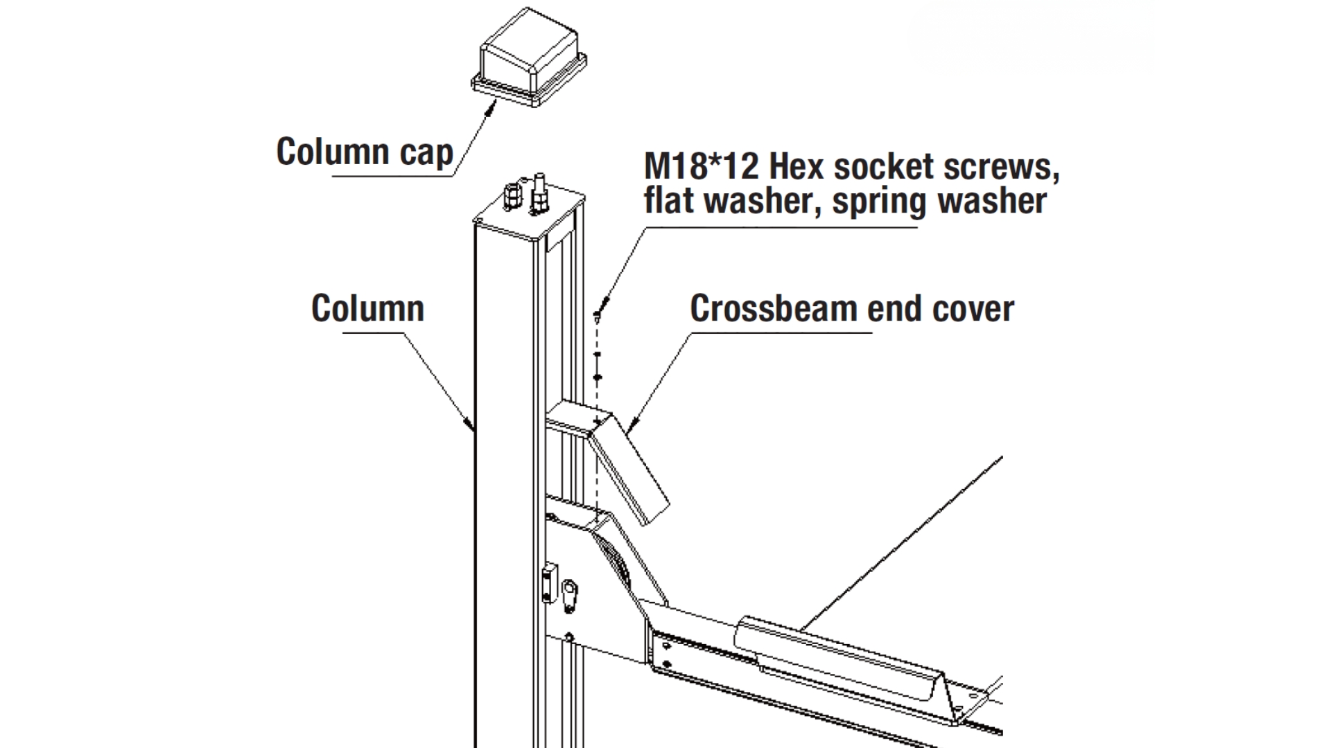
Step 12: Assemble the Column Cap and Crossbeam End Cover
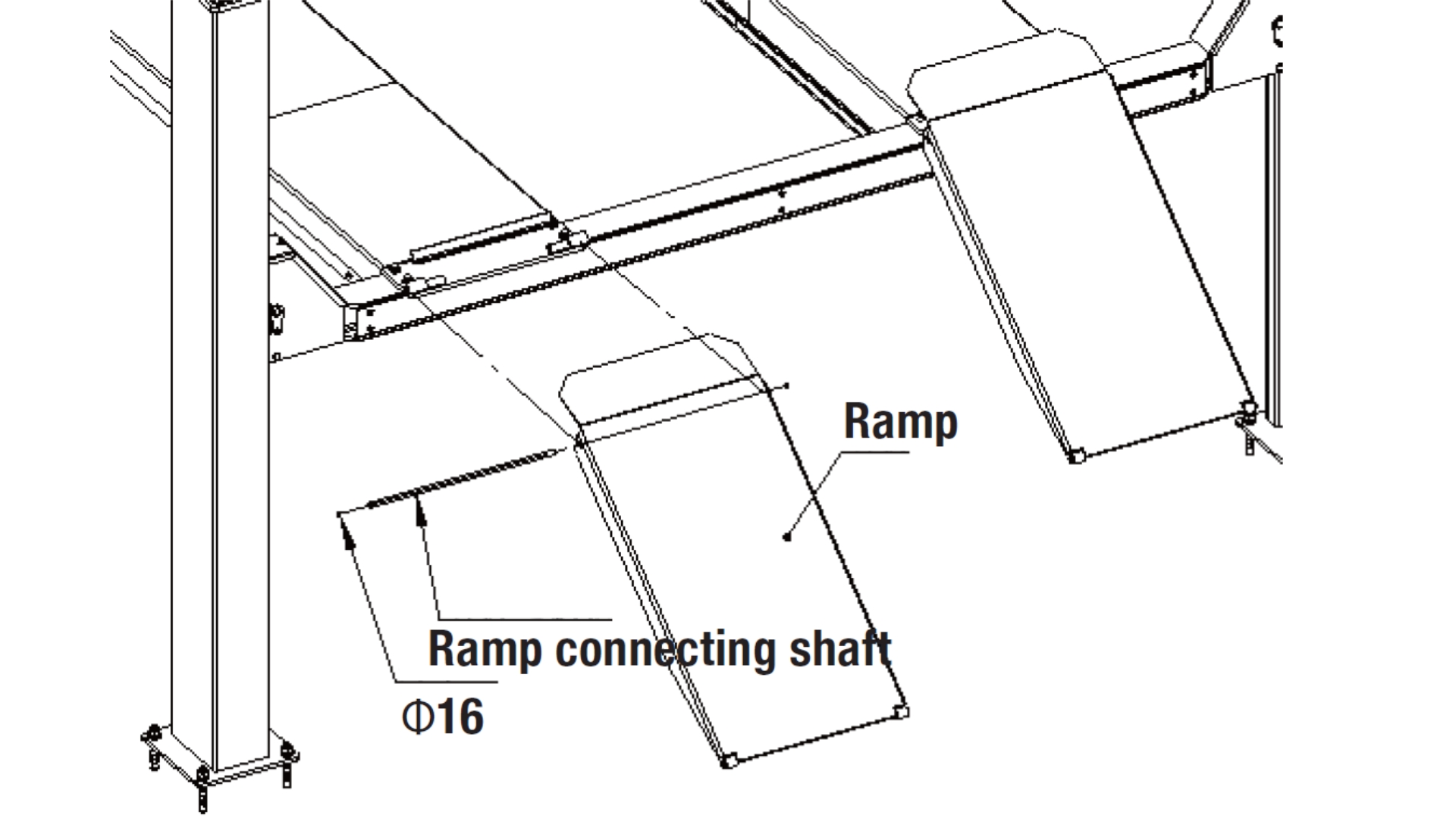
Step 13: Assemble the Ramps
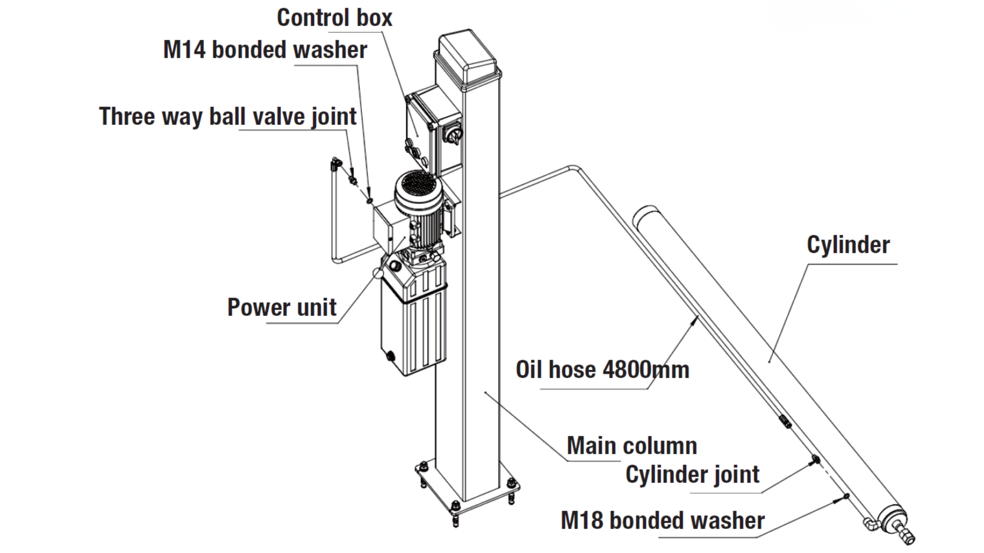
Step 14: Assemble the Oil Hose and Joints
Step 15: Assemble the Secondary Lifting Machine – Rolling Jack (Optional)
Optional, not included – needs to be purchased separately.
1) Dimension drawing as below:
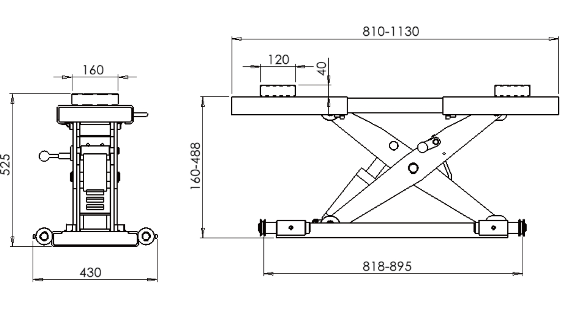
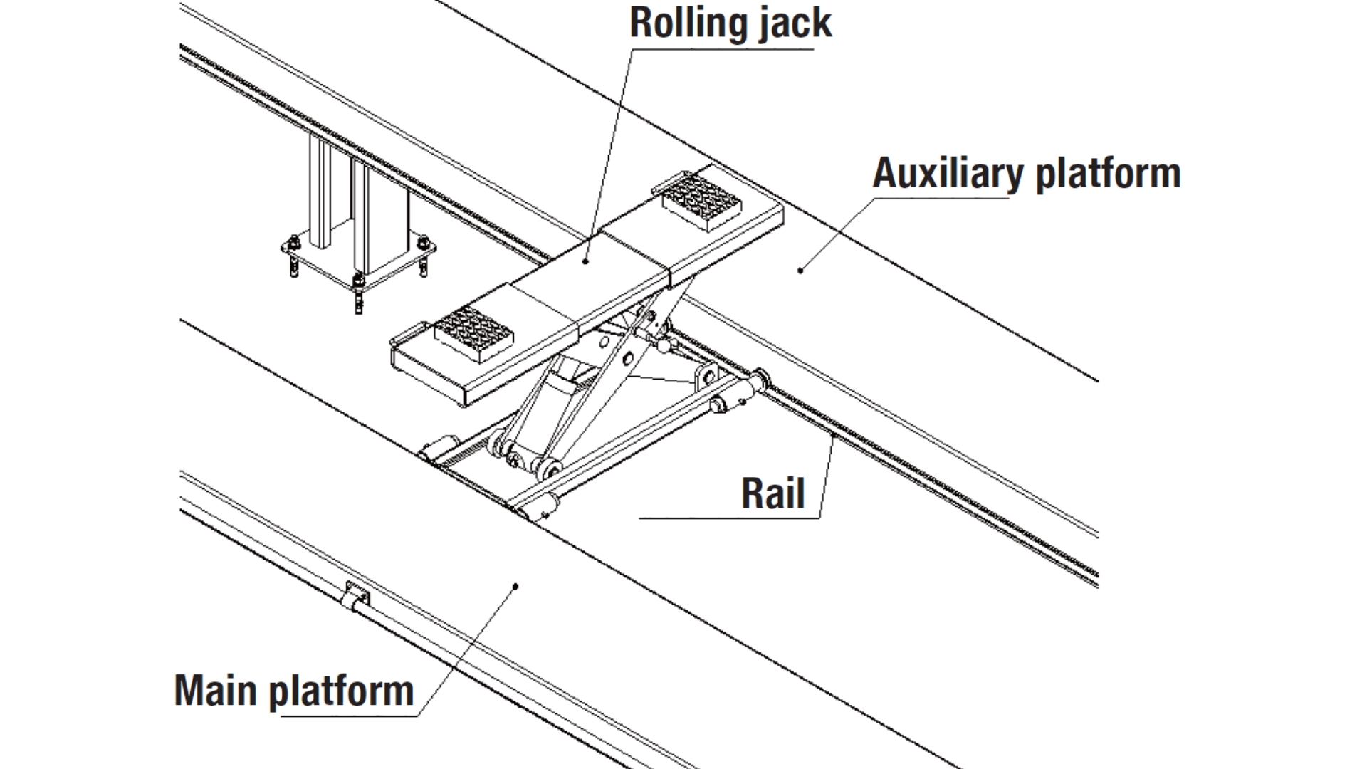
2) Assembling of the rolling jack: Put the rolling jack onto the rail of platforms. The auxiliary platform is adjustable to adjust the distance of platforms based on different vehicles' maintenance needs. And the adjusting distance achieved by the rolling jack's extending, the range is: 818–928mm.
Step 16: Filling in the Hydraulic Oil
Note
When the actual temperature is above 18 degrees Celsius, it is recommended to use #46 anti-wear hydraulic oil; when the temperature is below 18 degrees Celsius, it is recommended to use #32 anti-wear hydraulic oil. The viscosity of the hydraulic oil largely determines the lifting speed of the lift.
The oil tank has a capacity of 12L and usually only needs to be filled to 80%.
Step 17: Connecting the Power Supply
CAUTION!
Only electrical professionals are permitted to connect the power supply.
Step 18: Synchronisation (Adjust the Four Points to be Even)
CAUTION!
Please don't stop a car on the lift while synchronising.
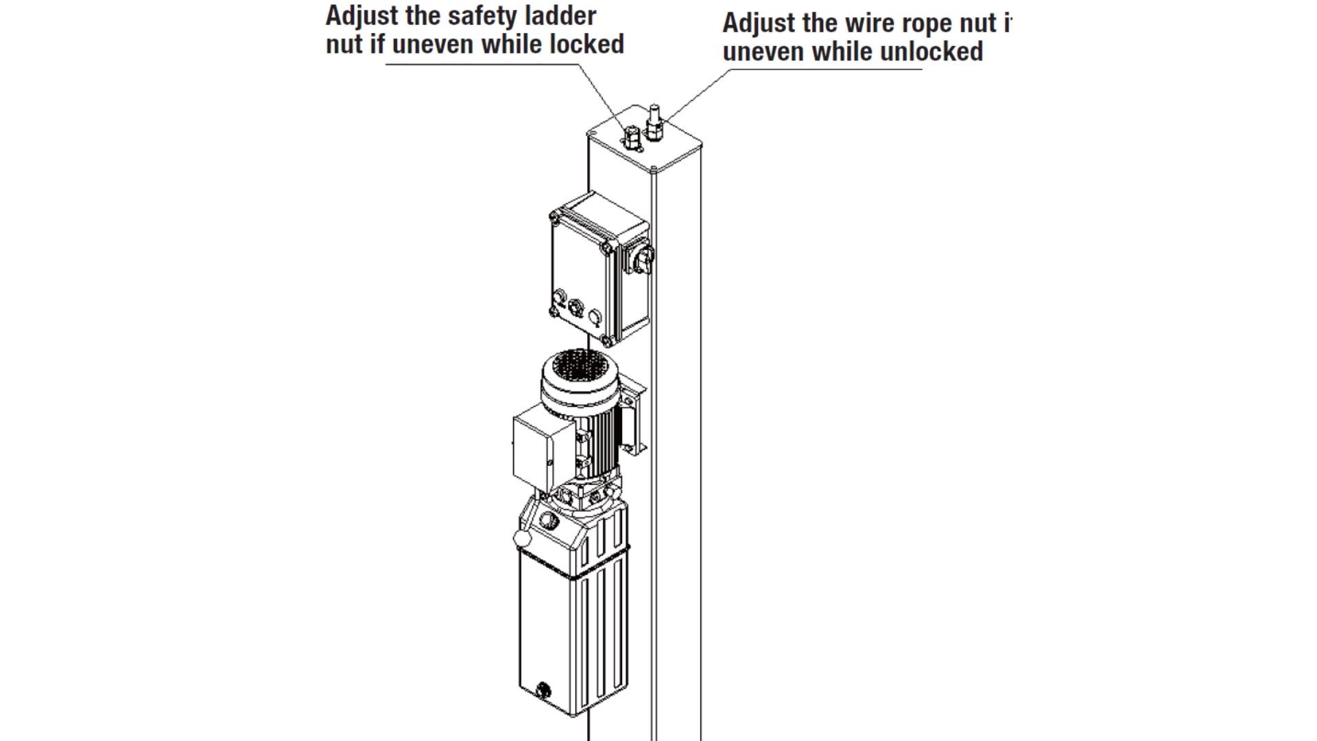
A: Synchronisation of the whole lift.
Turn on the main power switch on the control box, release the emergency stop switch, press the UP button, and after the wire rope is fully tightened, measure whether the distance from the ends of the two crossbeams to the base plate of the main and auxiliary columns is equal. If they are not equal, adjust the wire rope nuts at the top of the columns until the distance from the four ends of the two crossbeams to the base plate is consistent.
B: Synchronisation of the safety.
Press the lock button to lower the lift until the safety mechanism is engaged. At this point, the wire rope is slack. Measure the distance from the ends of the two crossbeams to the base plate of the main and auxiliary columns. If they are not equal, adjust the safety ladder nut at the top of the column until the distance from the four ends of the two crossbeams to the base plate is consistent.
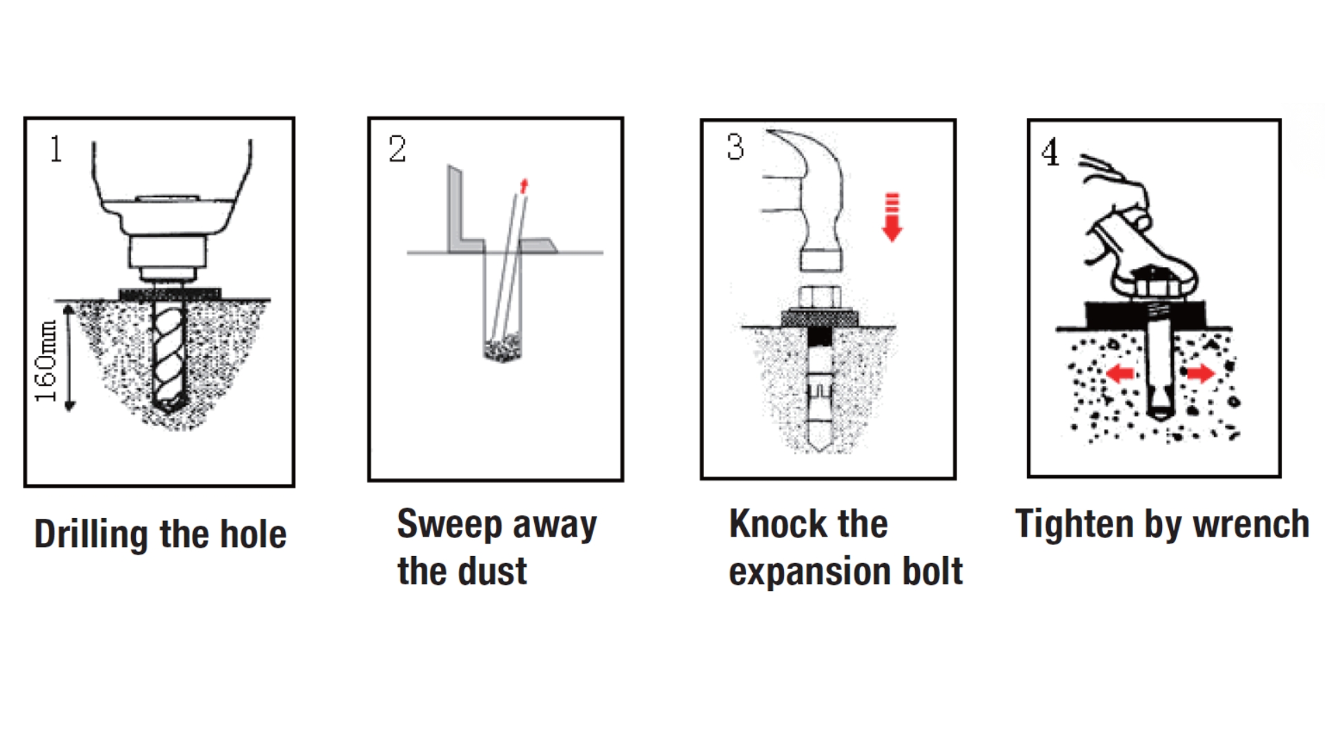
Step 19: Assemble the Anchor Bolts
- Use a hammer drill to drill holes for the expansion bolts, applying force vertically and ensuring the drill bit is not tilted.
- After drilling, sweep away any dust, ensuring the base plate of the column is accurately positioned relative to other columns during drilling.
- If the base plate requires shims to ensure levelness, insert appropriately sized shims. This will ensure the column is perpendicular to the ground after the expansion bolts are tightened. After inserting the shims, begin tightening the expansion anchor bolts.
- Install the auxiliary columns following steps 1), 2), and 3).
Attention
The above steps are all installation steps of the four post lift. The manufacturer is committed to continuously improving product quality and updating technical specifications without prior notice.
4. Check Notes After Installation
- Whether the column is perpendicular to the ground
- Whether the main and sub columns are parallel
- Whether the hoses are well connected
- Whether the steel cable are well connected
- Whether the lifting arms are installed in place
- Whether the electrical connections are correct
- Whether the other parts are fastening well
- Whether the necessary lubricating parts are well lubricated
Appendix B: Parts List & Exploded Diagram
Enclosure 1: Packing List
Main Components
| No. | Name | Source | Qty. | Remarks |
|---|---|---|---|---|
| 1 | Main platform | Assembly parts | 1 | |
| 2 | Auxiliary platform | Assembly parts | 1 | |
| 3 | Main column | Assembly parts | 1 | |
| 4 | Auxiliary column | Assembly parts | 3 | |
| 5 | Main crossbeam assembly | Assembly parts | 1 | |
| 6 | Auxiliary crossbeam assembly | Assembly parts | 1 | |
| 7 | Ramp | Assembly parts | 2 | |
| 8 | Stop plate | Assembly parts | 2 | |
| 9 | Power unit | Outsourcing | 1 | 230V |
| 10 | Control box | 1 |
Accessories Box
| No. | Figure No. | Name | Source | Qty. | Remarks |
|---|---|---|---|---|---|
| 1 | – | M16*120 anchor bolts | Outsourcing | 16 | Galvanized |
| 2 | 4SF-4000BA-2000-24 | Crossbeam ends cover | Outsourcing | 4 | |
| 3 | – | M8*12 Hex socket screws | Standard | 4 | Galvanized |
| 4 | – | M8 spring washer | Standard | 8 | Galvanized |
| 5 | – | M8 flat washer | Standard | 8 | Galvanized |
| 6 | 4SF-4000BA-1000-04 | Column cap | Outsourcing | 4 | |
| 7 | 4SF-4000BA-2000-21 | Wire rope limit shaft | Outsourcing | 4 | Galvanized |
| 8 | – | Φ16 circlip | Standard | 8 | |
| 9 | – | M8*25 Hex socket screws | Standard | 4 | Galvanized |
| 10 | – | M8 nut | Standard | 4 | Galvanized |
| 11 | – | M12*20 external hex screws | Standard | 4 | Galvanized |
| 12 | – | M12*25 external hex screws | Standard | 8 | Galvanized |
| 13 | – | M12 spring washer | Standard | 12 | Galvanized |
| 14 | – | M12 flat washer | Standard | 12 | Galvanized |
| 15 | 4SF-4000B-A-6000-03 | Cylinder joint | Outsourcing | 1 | Galvanized |
| 16 | 4SF-4000CK-3000-01 | Rubber tire block | Outsourcing | 4 | |
| 17 | SF-E3500-A-10000-10 | Square rubber pad | Outsourcing | 2 | |
| 18 | – | 24V control box | Outsourcing | 1 | |
| 19 | – | M5*12 Phillips pan head screws | Outsourcing | 2 | Galvanized |
| 20 | SF-X2000-A-8000-02 | Oil hose 6200mm on rolling jack | Outsourcing | 1 | |
| 21 | SF-X2000-A-8000-05 | Motor joint | Outsourcing | 1 | Galvanized |
| 22 | SF-B4000-A-6000-09 | Three way ball valve joint | Outsourcing | 1 | |
| 23 | – | M14 bonded washer | Standard | 1 | |
| 24 | – | Manual | 1 | ||
| 25 | – | Limit Switch (8108) | Outsourcing | 1 |
Enclosure 2: Dimension
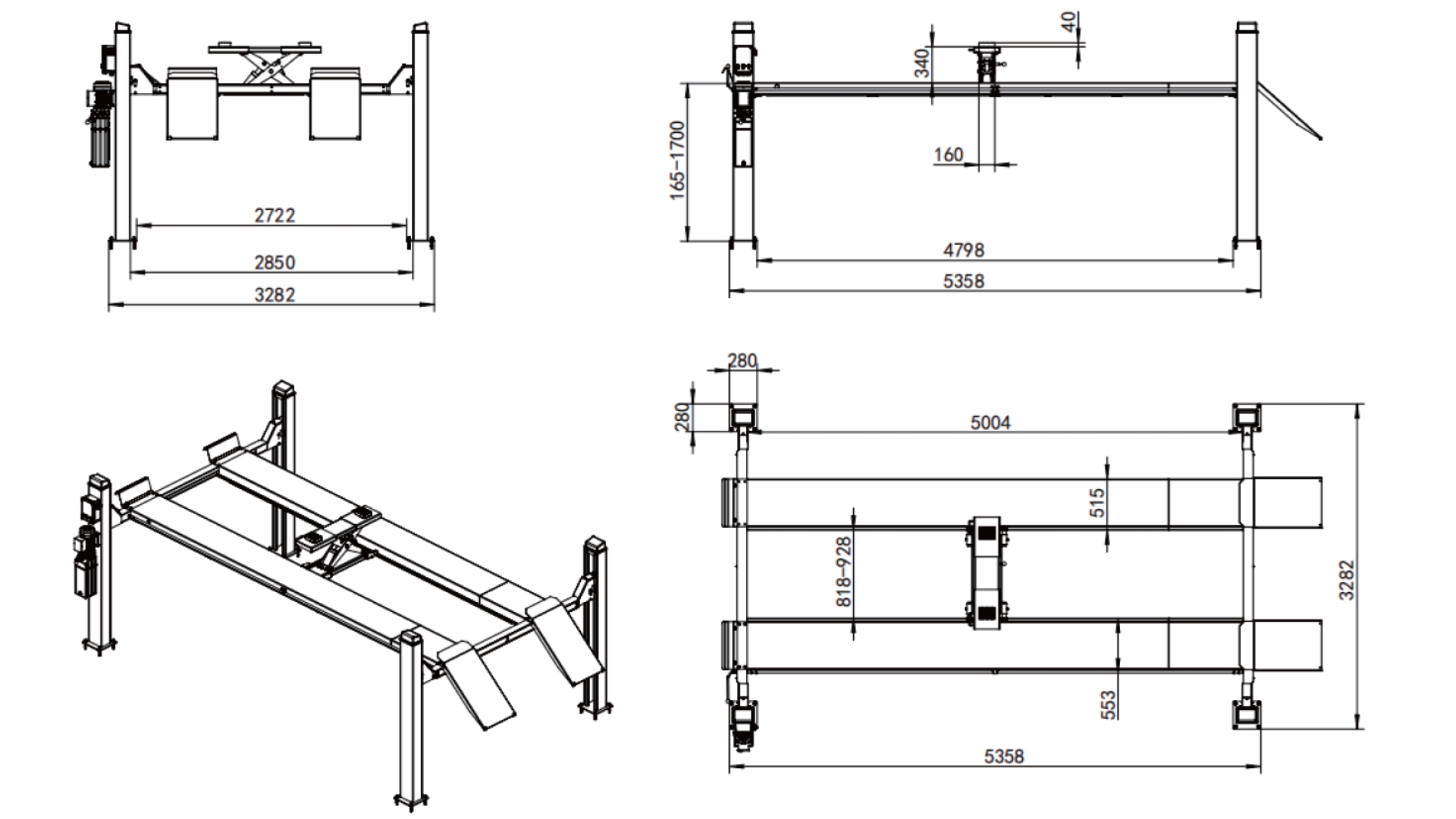
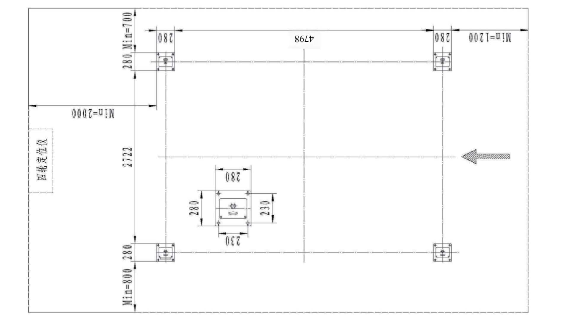
Enclosure 3: Foundation Installation Drawing
Enclosure 4: Hydraulic Schematic Diagram
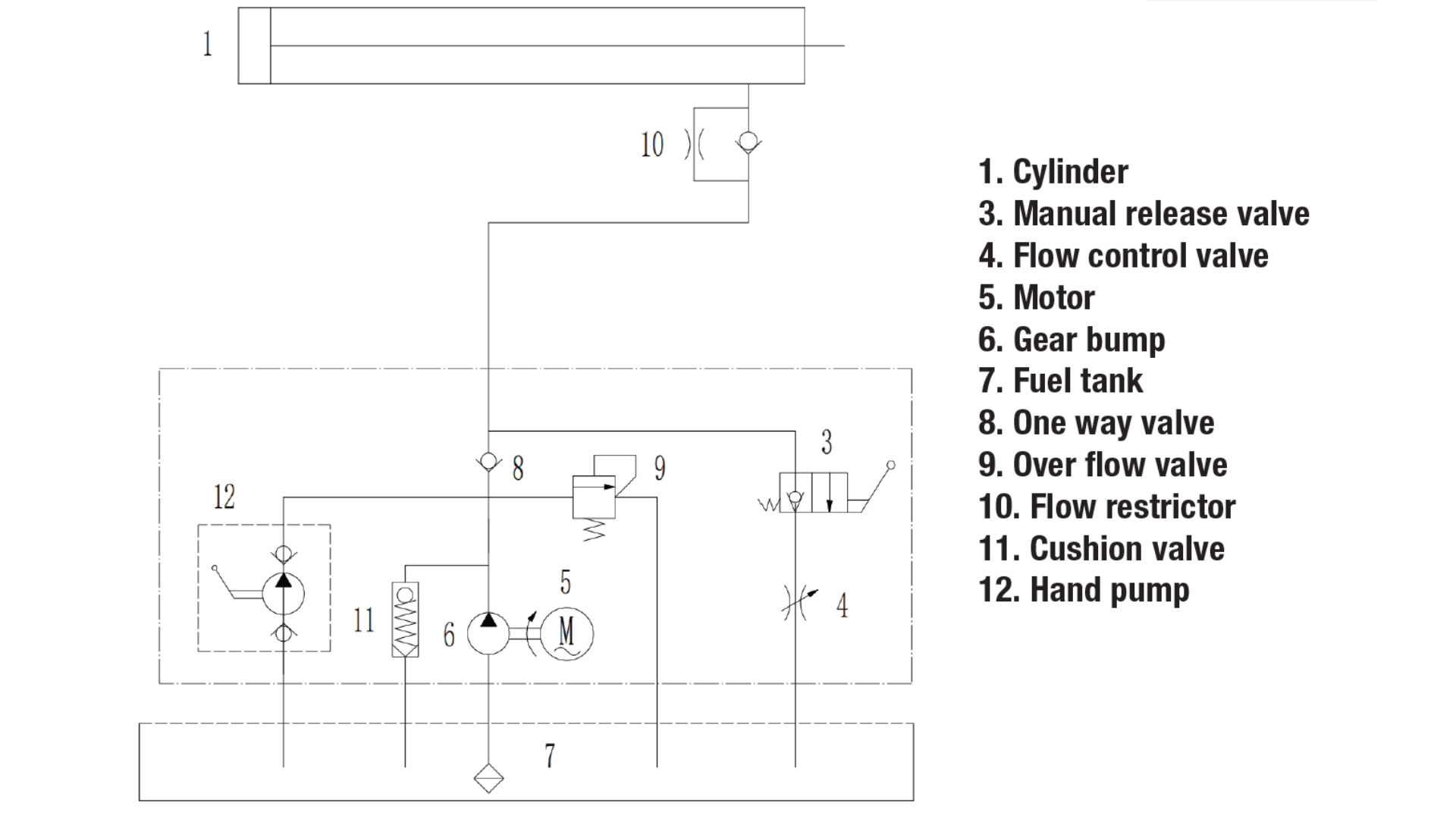
1. Cylinder
3. Manual release valve
4. Flow control valve
5. Motor
6. Gear pump
7. Fuel tank
8. One way valve
9. Over flow valve
10. Flow restrictor
11. Cushion valve
12. Hand pump
Enclosure 5: Electrical Schematic Diagram
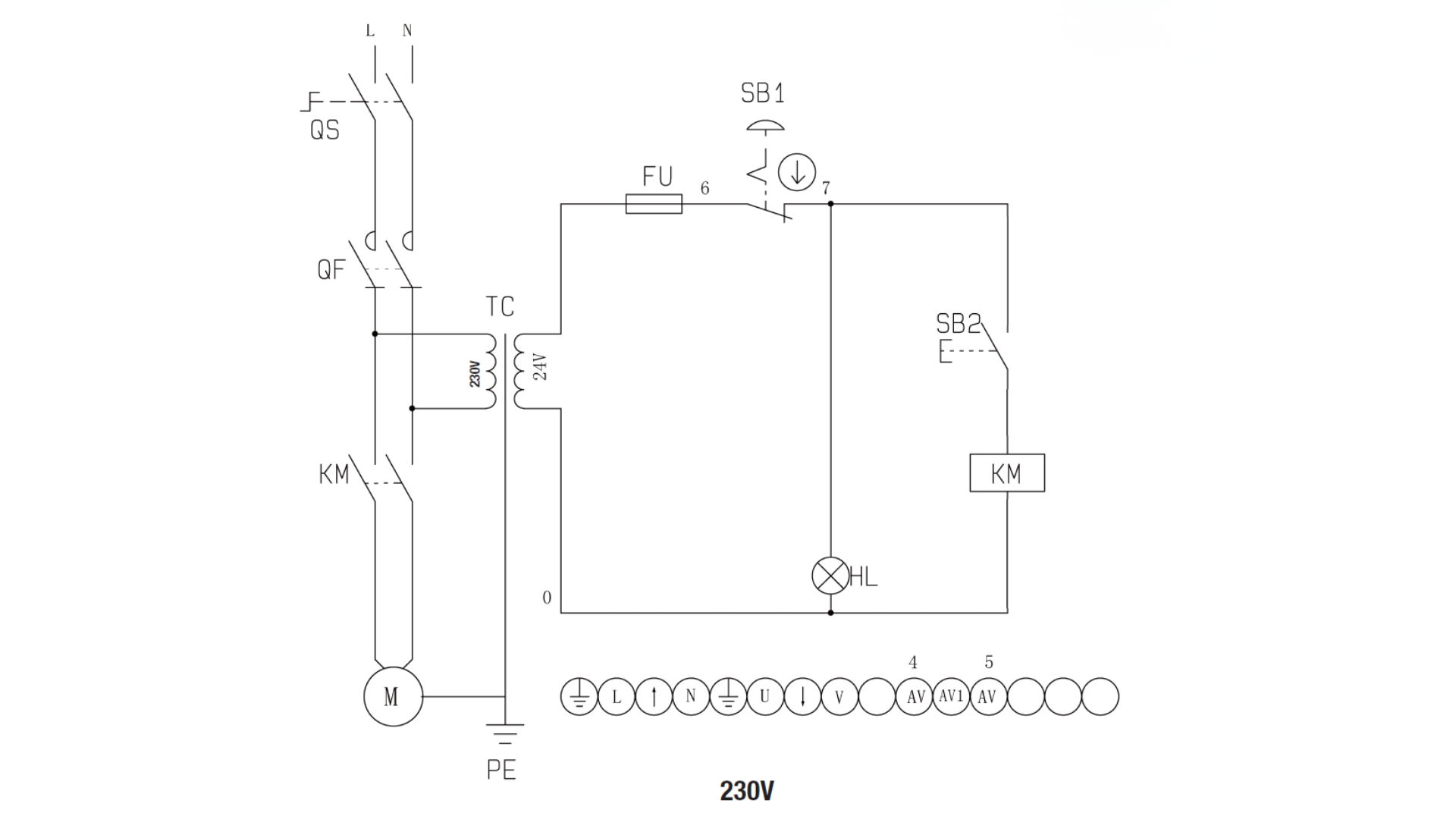
| Symbol | Description | Symbol | Description |
|---|---|---|---|
| QS | Main Switch | QF | Fuse |
| KM | AC contactor | TC | Transformer |
| FU | Fuse | SB1 | Emergency stop switch |
| SB2 | UP button | HL | Indicator light |
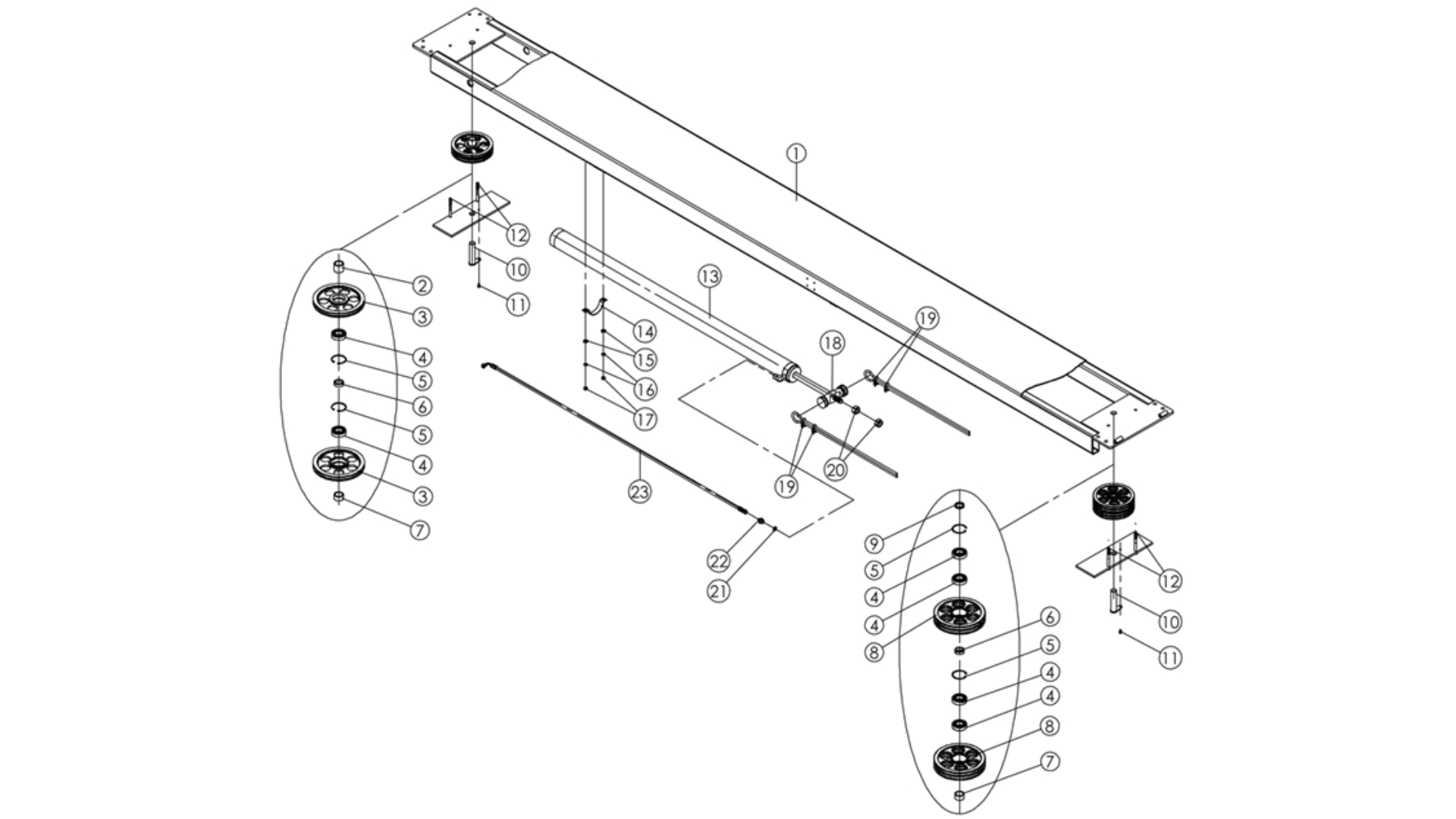
Enclosure 6: General Assembly Exploded View
| No. | Figure No. | Name | Qty | Remarks |
|---|---|---|---|---|
| 1 | SF-5000AP-B-01 | Main column assembly parts | 1 | Assembly parts |
| 2 | SF04010034 | Auxiliary column welding | 3 | Spray-coated parts |
| 3 | SF-5000AP-B-03 | Main crossbeam assembly parts | 1 | Assembly parts |
| 4 | SF-5000AP-B-04 | Auxiliary crossbeam assembly parts | 1 | Assembly parts |
| 5 | SF-5000AP-B-05 | Main bridge plate assembly parts | 1 | Assembly parts |
| 6 | SF04010080 | Auxiliary bridge plate assembly parts | 1 | Spray-coated parts |
| 7 | SF04010035 | Safety locker welding | 3 | Spray-coated parts |
| 8 | SF04020124 | Wheel stop plate | 2 | Spray-coated parts |
| 9 | SFB05012 | M12 flat washer | 12 | Galvanized parts |
| 10 | SFB06012 | M12 spring washer | 12 | Galvanized parts |
| 11 | SFB01012L25 | M12*25 hexagon head screw | 8 | Galvanized parts |
| 12 | SFB01012L20 | M12*20 hexagon head screw | 4 | Galvanized parts |
| 13 | SFA120058 | Rubber wheel chock | 4 | Rubber |
| 14 | SFB11016L120 | M16*120 anchor bolts | 16 | Galvanized parts |
| 15 | SF04020151 | Safety drive rod | 1 | Galvanized parts |
| 16 | SF04010044 | Drive rod fixing plate welding | 1 | Spray-coated parts |
| 17 | SFB02006L12 | M6*12 Hexagon socket head cap screws | 4 | Galvanized parts |
| 18 | SFB02008L30 | M8*30 Hexagon socket head cap screws | 4 | Galvanized parts |
| 19 | SFB05020 | M20 Flat washer | 6 | Galvanized parts |
| 20 | SFB07020 | M20 Nut | 12 | Galvanized parts |
| 21 | SFA120051 | Column top cap | 4 | Plastic |
| 22 | SFA070028 | 13150mm cable | 2 | Galvanized parts |
| 23 | SFB30010L30 | M10*30 Round head square neck screw | 3 | Galvanized parts |
| 24 | SFB05010 | M10 Flat washer | 3 | Galvanized parts |
| 25 | SFB06010 | M10 Spring washer | 3 | Galvanized parts |
| 26 | SFB07010 | M10 Nut | 3 | Galvanized parts |
| 27 | SF04010071 | Ramps welding | 2 | Spray-coated parts |
| 28 | SFA080338 | Connecting axle for ramps | 2 | Spray-coated parts |
| 29 | SFA080339 | Rollers for ramps | 4 | Spray-coated parts |
| 30 | SFB09012 | Ø12 Wild card | 8 | Spray-coated parts |
Enclosure 7: Exploded View of Main Column Assembly
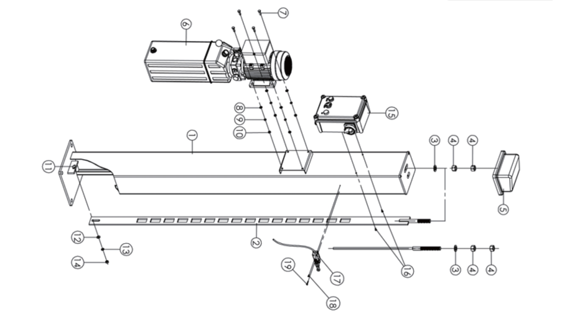
| No. | Figure No. | Name | Qty | Remark |
|---|---|---|---|---|
| 1 | SF04010117 | Main column welding | 1 | Spray-coated parts |
| 2 | SF04010035 | Safety locker welding | 1 | Spray-coated parts |
| 3 | SFB05020 | M20 Flat washer | 2 | Galvanized parts |
| 4 | SFB07020 | M20 Nut | 4 | Galvanized parts |
| 5 | SFA120051 | Column top cap | 1 | Black plastic |
| 6 | SFA01-01B-15 | 12L Power unit | 1 | |
| 7 | SFB01008L25 | M8*25 Hexagon socket head cap screws | 4 | Galvanized parts |
| 8 | SFB05008 | M8 Flat washer | 4 | Galvanized parts |
| 9 | SFB06008 | M8 Spring washer | 4 | Galvanized parts |
| 10 | SFB07008 | M8 Nut | 4 | Galvanized parts |
| 11 | SFB30010L30 | M10*30 Round head square neck screw | 1 | Galvanized parts |
| 12 | SFB05010 | M10 Flat washer | 1 | Galvanized parts |
| 13 | SFB06010 | M10 Spring washer | 1 | Galvanized parts |
| 14 | SFB07010 | M10 Nut | 1 | Galvanized parts |
| 15 | SFA02-02AA-02 | 24V Control box | 1 | Optional |
| 16 | SFB04005L12 | M5*12 Phillips pan head screw | 2 | Galvanized parts (Optional) |
| 17 | SFA020000D47 | Limit switch | 1 | Optional |
| 18 | SFB04004L12 | M4*12 Phillips pan head screw | 1 | Galvanized parts (Optional) |
| 19 | SFB04004L25 | M4*25 Phillips pan head screw | 1 | Galvanized parts (Optional) |
Enclosure 8: 12L Power Unit
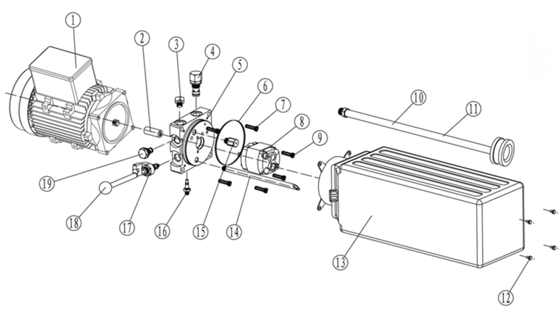
| No. | Figure No. | Name | Specification | Qty | Remark |
|---|---|---|---|---|---|
| 1A | SFI02B-025-DF | 220V motor | 220V/50HZ/3KW/1PH | 1 | Iron or Alu |
| 1B | SFI02B-026-DF | 380V motor | 380V/50HZ/3KW/3PH | 1 | As per choice |
| 2 | SFI02H0001-DF | Coupling | (DF) | 1 | 9-tooth spline coupling |
| 3 | SFA060036 | Cylinder blind plug | M14*1.5 | 1 | |
| 4 | SFI02G0001-DF | Relief valve | (DF) | 1 | |
| 5 | SFI02R0002-DF | Power unit valve plate | (DF) | 1 | |
| 6 | SFI02N0001-DF | O-ring for valve plate | 109*5.3 | 1 | Rubber |
| 7 | SFB02006L20 | Hexagon socket head cap screws | M6*20 | 4 | Galvanized parts |
| 8A | SFI02O0001-DF | 4T, 220V Gear pump | CBK-F 2.1F | 1 | As per choice |
| 8B | SFI02O0002-DF | 4T, 380V Gear pump | CBK-F 2.5F | 1 | |
| 9 | SFB02008L75 | Hexagon socket head cap screws | M8*75 | 4 | Galvanized parts |
| 10 | SFI02V-0002-DF-12L | Oil return hose | 12L | 1 | |
| 11 | SFI02S0002-DF | Oil drum filter screen | (DF) | 1 | |
| 12 | SFB01006L12 | Hexagon head screw | M6*12 | 4 | Galvanized parts |
| 13 | SFI03-SL-DF-12L | Plastic tank | 12L | 1 | |
| 14 | SFI02J0001-DF-12L | Oil return hose | 12L | 1 | |
| 15 | SFI02U-0002-DF | Buffer valve | (DF) | 1 | |
| 16 | SFI02R0002-DF | Flow control valve | (DF) | 1 | |
| 17 | SFI02F0002-DF | Manual unloading valve | (DF) | 1 | |
| 18 | SFI02Q0002 | Handle | (DF) | 1 | |
| 19 | SFI02C-001-DF | One-way valve | (DF) | 1 |
Enclosure 9: Exploded View of Crossbeam
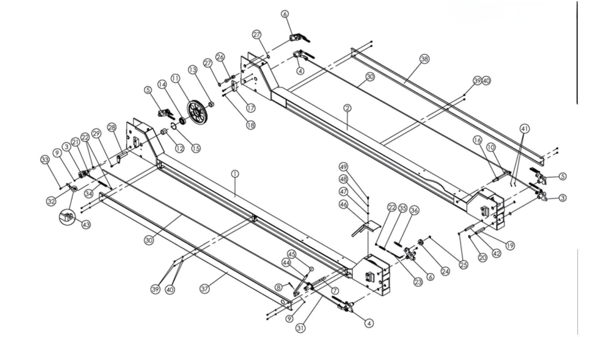
| No. | Figure No. | Name | Qty | Remark |
|---|---|---|---|---|
| 1 | SF04010036 | Main crossbeam welding | 1 | Spray-coated parts |
| 2 | SF04010037 | Auxiliary crossbeam welding | 1 | Spray-coated parts |
| 3 | SFA080306 | Main safety welding A | 2 | Galvanized parts |
| 4 | SFA080307 | Main safety welding B | 2 | Galvanized parts |
| 5 | SFA080308 | Welding of rope breakage safety lock A | 2 | Galvanized parts |
| 6 | SFA080309 | Welding of rope breakage safety lock B | 2 | Galvanized parts |
| 7 | SFA080310 | Welding of the safety connecting shaft for main crossbeam | 1 | Galvanized parts |
| 8 | SFB02006L40 | M6*40 Hexagon socket head cap screws | 1 | Galvanized parts |
| 9 | SFB07006B | M6 Lock nut | 5 | Galvanized parts |
| 10 | SFA080311 | Welding of the safety connecting shaft for auxiliary crossbeam | 1 | Galvanized parts |
| 11 | SFA080313 | Single-sheave rope wheel | 4 | Castings |
| 12 | SFA080314 | Rope wheel spacer sleeve 1 | 4 | Galvanized parts |
| 13 | SFA080315 | Rope wheel spacer sleeve 2 | 4 | Galvanized parts |
| 14 | SFB21-6206 | Shaft 6206 | 4 | |
| 15 | SFB10062 | Circlip 62 | 4 | Black oxide finish parts |
| 16 | SFA080316 | Safety handle spacer sleeve | 2 | Galvanized parts |
| 17 | SFA090020 | Slider for crossbeam end | 8 | White-coated component |
| 18 | SFB02008L25 | M8*25 Hexagon socket head cap screws | 17 | Galvanized parts |
| 19 | SFA080317 | Safety shaft | 8 | Galvanized parts |
| 20 | SFB09019 | Ø19 | 16 | Black oxide finish parts |
| 21 | SFA080318 | Main safety spring pull rod | 4 | Galvanized parts |
| 22 | SFB07008B | M8 Lock nut | 8 | Galvanized parts |
| 23 | SFA080319 | Rope breakage safety spring pull rod | 4 | Galvanized parts |
| 24 | SFA080320 | Rope breakage safety small shaft wheel | 4 | Galvanized parts |
| 25 | SFB09016 | Ø16 External circlip | 12 | Black oxide finish parts |
| 26 | SFA080321 | Safety lock limited shaft | 4 | Galvanized parts |
| 27 | SFB09025 | Ø25 External circlip | 8 | Black oxide finish parts |
| 28 | SFA080322 | Welding of crossbeam rope wheel shaft | 4 | Galvanized parts |
| 29 | SFB02008L12 | M8*12 Hexagon socket head cap screws | 4 | Galvanized parts |
| 30 | SFA080323 | Welding of long unlocking pull rod | 2 | Galvanized parts |
| 31 | SFA080324 | Welding of short unlocking pull rod | 2 | Galvanized parts |
| 32 | SF04020097 | Safety connecting plate | 5 | Spray-coated parts |
| 33 | SFB04006L20 | M6*20 Phillips pan head screw | 4 | Galvanized parts |
| 34 | SFA130016 | Spring for main safety lock | 4 | Black oxide finish parts |
| 35 | SFA130017 | Compression spring for rope breakage | 4 | Black oxide finish parts |
| 36 | SFA130012 | Tension spring for rope breakage | 4 | Black oxide finish parts |
| 37 | SF04020099 | Cover for auxiliary crossbeam | 1 | Spray-coated parts |
| 38 | SF04020100 | Cover for auxiliary crossbeam | 1 | Spray-coated parts |
| 39 | SFB04006L10 | M6*10 Phillips pan head screw | 12 | Galvanized parts |
| 40 | SFB05006 | M6 Flat washer | 12 | Galvanized parts |
| 41 | SFB13002.5L28 | Ø2.5*28 Cotter pin | 8 | Galvanized parts |
| 42 | SFA080325 | Wire rope limit shaft | 4 | Galvanized parts |
| 43 | SFB07008 | M8 Nut | 8 | Galvanized parts |
| 44 | SFA080312 | Safety handle welding | 1 | Galvanized parts |
| 45 | SFA120019 | Bakelite ball | 1 | Black |
| 46 | SFA080326 | Crossbeam end cover | 4 | Spray-coated parts |
| 47 | SFB02008L12 | M8*12 Hexagon socket head cap screws | 4 | Galvanized parts |
| 48 | SFB05008 | M8 Flat washer | 5 | Galvanized parts |
| 49 | SFB06008 | M8 Spring washer | 5 | Galvanized parts |
Enclosure 10: Exploded View of Main Bridge Assembly
| No. | Figure No. | Name | Qty | Remark |
|---|---|---|---|---|
| 1 | SF04010079 | Welding of main bridge | 1 | Spray-coated parts |
| 2 | SFA080314 | Rope wheel spacer sleeve 1 | 1 | Galvanized parts |
| 3 | SFA080313 | Single-Sheave Wire Rope Pulley | 2 | Castings |
| 4 | SFB21-6206 | Shaft 6206 | 5 | |
| 5 | SFB10062 | Circlip 62 | 4 | Black oxide finish part |
| 6 | SFA080333 | Bridge spacer sleeve | 2 | Galvanized parts |
| 7 | SFA080315 | Rope wheel spacer sleeve 2 | 2 | Galvanized parts |
| 8 | SFA080330 | Double-Sheave Wire Rope Pulley for Bridge Plate | 2 | Cast parts |
| 9 | SFA080332 | Bridge spacer sleeve 1 | 1 | Galvanized parts |
| 10 | SFA080374 | Welding of bridge rope wheel shaft | 2 | Galvanized parts |
| 11 | SFB02008L12 | M8*12 Hexagon socket head cap screws | 2 | Galvanized parts |
| 12 | SFB01012L130 | M12*130 hexagon head screw | 4 | Galvanized parts |
| 13 | SFA040031 | Oil cylinder | 1 | Assembly parts |
| 14 | SF04020165 | Oil cylinder fixing ring | 1 | Spray-coated parts |
| 15 | SFB05012 | M12 Flat washer | 2 | Galvanized parts |
| 16 | SFB06012 | M12 Spring washer | 2 | Galvanized parts |
| 17 | SFB07012 | M12 Nut | 2 | Galvanized parts |
| 18 | SFA080335 | Wire rope fastener | 1 | Galvanized parts |
| 19 | SFB22002 | M12 U type Wire rope clip | 4 | Galvanized parts |
| 20 | SFB07024 | M24 Nut (M24*1.5) | 2 | Galvanized parts |
| 21 | SFB14018 | M18 Combination gasket | 1 | |
| 22 | SFA060026 | Cylinder connector | 1 | Galvanized parts |
| 23 | SFA050061 | 4800mm hose for main lift | 1 |
DANGER! Read all safety regulations and instructions.
Keep all safety regulations and instructions in a safe place for future use.
Supplied by:
Adendorff Machinery Mart
98 Sailor Malan Avenue, Aeroton, Johannesburg, 2190
www.adendorff.co.za
Made in P.R.C.