What You Need to Know About Centrifugal Pumps! | A Practical Guide
Listen to a podcast about this article
What You Need to Know About Centrifugal Pumps! | A Practical Guide
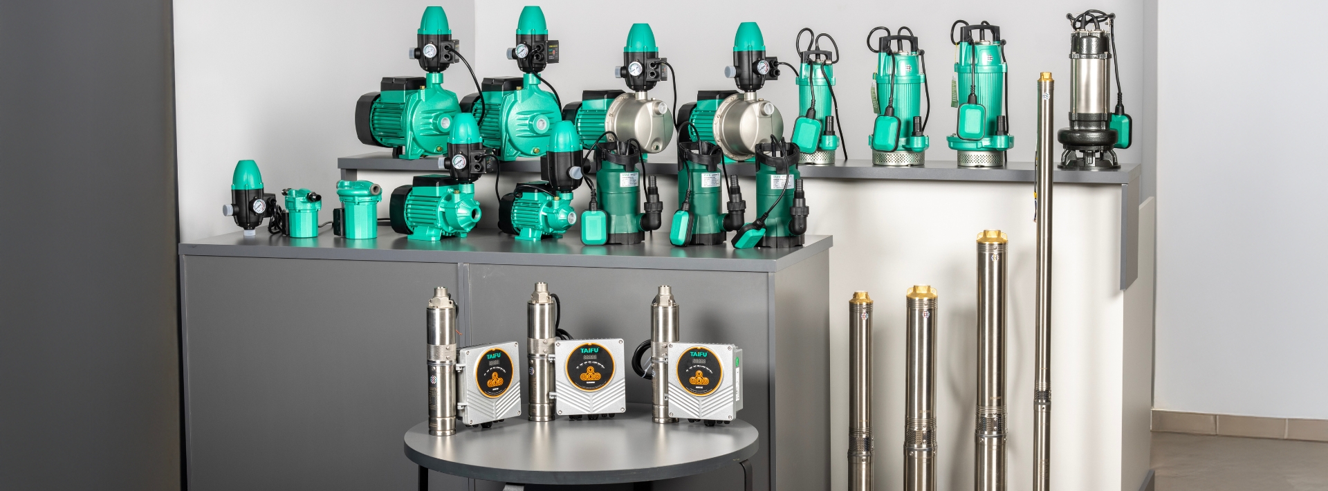
Table of Contents
- 1. Introduction
- 2. Understanding Forces in Centrifugal Pumps
- 3. Anatomy of Centrifugal Pumps
- 4. Types of Centrifugal Pumps
- 5. How Centrifugal Pumps Work
- 6. Pump Selection
- 7. Name Plates
- 8. Pump Curves
- 9. Friction Graphs
- 10. Total Dynamic Head (TDH)
- 11. Installation of Centrifugal Pumps
- 12. Maintenance and Troubleshooting
- 13. Basic Principles and Definitions
1. Introduction to Centrifugal Pumps
1.1. Centrifugal Pump History
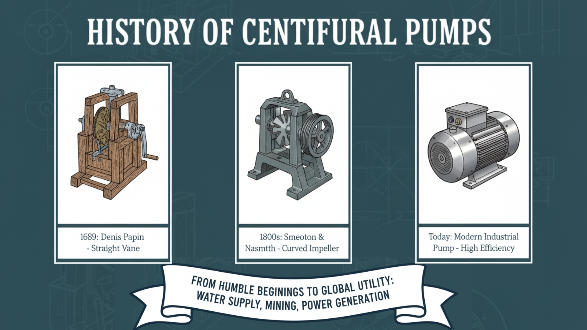
The centrifugal pump has a rich history of innovation dating back to the 17th century. Denis Papin's early invention in 1689 laid the groundwork for future developments, with subsequent improvements by John Smeaton and James Nasmyth, who introduced a curved vane impeller to enhance efficiency and reliability. Over time, advances in materials and design further refined their performance, resulting in more efficient, compact, and durable pumps. Today, centrifugal pumps are the most widely used pump and play a vital role in various industrial applications including water supply, mining, and power generation. Their evolution has made them a crucial component in many industries, with continued innovations enhancing their reliability and efficiency.
Timeline
1689 - The First Centrifugal Pump
- Denis Papin, a French physicist, invented the first centrifugal pump.
- Papin's design used a spinning impeller to throw water outward, creating pressure.
- However, his pump was not practical for widespread use due to its complexity and inefficiency.
1700s-1800s - Improvements & Experimentation
- Over the next century, various inventors and engineers experimented with centrifugal pump designs.
- In 1775, English engineer John Smeaton built a more efficient centrifugal pump, but it still had limitations.
1838 - Breakthrough & Patents
- Irish engineer James Nasmyth patented a centrifugal pump with a curved vane impeller.
- Nasmyth's design improved efficiency and reliability, making centrifugal pumps more viable for industrial applications.
- Other innovators, like Daniel Bernoulli and Leonhard Euler, contributed to the understanding of fluid dynamics and pump design.
Late 19th Century - Industrialisation & Adoption
- Centrifugal pumps became widely used in industrial applications, such as water supply systems, mining operations, power generation plants and manufacturing processes.
- The introduction of steam power and later, electric motors, enabled centrifugal pumps to operate more efficiently and reliably.
Early 20th Century - Advancements & Innovations
- Advances in materials science led to the development of cast iron and steel pumps as well as stainless steel and alloy pumps for corrosive applications.
- Design improvements included:
- More efficient impeller designs
- Better sealing technologies
- Compact and modular designs
- The introduction of variable speed drives and controls enabled more precise flow control and efficiency optimisation.
Mid-20th Century-Present - Modern Developments
- Centrifugal pumps continue to evolve with advances in materials science, computational fluid dynamics and simulation tools, energy efficiency and sustainability, and digitalisation and smart technologies.
- Modern centrifugal pumps are used in a wide range of applications, from small-scale industrial processes to large-scale infrastructure projects.
1.2. What Is a Centrifugal Pump?
A centrifugal pump is a type of pump that uses centrifugal force to transfer fluids. They offer versatility in various sizes, ranging from small, portable models to large, industrial-scale units. Manufacturers construct centrifugal pumps from a range of materials, including cast iron, stainless steel and aluminium, to tailor them to suit specific needs.
Engineers can install centrifugal pumps either horizontally or vertically depending on their application or installation site. To prevent overheating, they may require cooling systems or ventilation, and some are cooled by the fluid surrounding them. Additionally, they can be equipped with control systems, such as valves and sensors, to monitor and regulate their operation and allowing for precise management and automation.
1.3. Applications / Uses of Centrifugal Pumps
Centrifugal pumps are used in various settings across domestic, commercial and industrial settings. From supplying water to homes and businesses to circulating fluids in industrial processes, they play a crucial role in ensuring efficient fluid transfer.
| Industry/Application | Description |
|---|---|
| Water supply | Distribution of water for drinking, irrigation, and industrial processes. |
| Wastewater treatment | Handling and processing of wastewater, sewage, and effluent. |
| Chemical processing | Transfer and circulation of chemicals, acids, and bases |
| Oil and gas | Extraction, refining, and transportation of oil and gas. |
| Power generation | Cooling systems, boiler feedwater, and condensate return. |
| Industrial processes | Manufacturing, processing, and transfer of fluids in various industries. |
| Mining | Dewatering, slurry transport, and water supply |
| HVAC | Heating, ventilation, and air conditioning systems |
| Agriculture | Irrigation, livestock watering, and crop processing |
| Marine | Bilge pumping, ballast water management, and cooling systems on ships. |
Centrifugal pumps are favoured for their efficiency and versatility. They can handle large fluid volumes at high pressures with smooth flow, minimising energy losses. Their simple design ensures low maintenance and ease of use. They can pump various types of fluids such as water, chemicals, and slurries. They are cost-effective and provide consistent delivery. Some are self-priming, eliminating the need for manual air removal.
2. Understanding Forces in Centrifugal Pumps
2.1. Centrifugal Forces
A centrifugal pump is a rotary machine that is used to accelerate fluid through centrifugal force. Centrifugal force is a (fictitious) force that pulls objects away from a central point when moving in a circular path.
Centrifugal force is the apparent force that pushes fluid away from the centre of rotation in a rotating system. In centrifugal pumps, this force is used to increase the pressure and move the fluid through the pump.
A simple example of how centrifugal force works would be to tie a ball to a string and spin it around in a circle. As you spin, the ball is pulled away from your hand, right? That is centrifugal force! It is like the ball is trying to fly away from the centre of the spin.
2.2. Fictitious Forces
Fictitious forces are imaginary forces, they are not real forces in the way that gravity or friction are and only seem to exist because you are in a non-inertial (accelerating) reference frame. They are not caused by anything physically pushing or pulling but are just a result of how an object is moving or spinning.
Centrifugal force is one type of these imaginary forces. For example, when you are spinning on a merry-go-round, from your perspective it feels as if there is a force pushing you outward, but this is just because you are in a rotating frame of reference.
When looking at the situation from an outside perspective, you will see that nothing is actually pushing you out. What is happening is that you are just trying to keep up with the spinning motion, and the centrifugal force is your way of describing why you feel like you are being pushed away from the centre.
3. Anatomy / Components of a Centrifugal Pump
The principle pumping unit of a centrifugal pump consists of the impeller and volute. However, the pump needs other mechanical components to support its operation, provide control, and ensure safe and efficient performance.
The material that the pump is made of is important as it is what determines the type and temperature of fluid that the pump can handle. Cast iron pumps are usually used for colder or ambient temperature fluids, whilst stainless steel pumps are usually used for hot fluid applications. The material of pump that you select should also depend on the fluid being pumped as they may not be compatible with one another and cause corrosion, erosion, contamination and other issues. Always check the pumps datasheet to determine what temperatures and types of fluid the pump can handle.
3.1. Impeller (Rotary element)
An impeller is a spinning component with blades or vanes. It receives fluid at its centre and spins the fluid outward between the vanes away from the centre, increases the fluid's velocity and energy, creating flow.
There are 3 types of impellers:
- Open Impeller- Impeller has no shroud, used for handling suspended solids or abrasive fluids.
- Semi-open Impeller- Impeller has a shroud on one side, used for handling liquids with solids, fibres, or abrasives.
- Closed Impeller- Impeller has a shroud on both sides, providing higher efficiency and suitable for clean fluids.
There are many other types of impellers that you may come across in the pump industry. There are many different shapes, sizes and materials that they can be made of. Some others include paddle impellers, open channel impellers, vortex impellers, propeller impellers and turbine impellers.
Just as the material of the pump is important as it affects the temperature and type of fluid that can be pumped, so does the material of the impeller. Impellers that are made of Noryl® (plastic), can usually only handle temperatures up to 50°C. Impellers made from brass can handle temperatures of up to 90°C and stainless-steel impellers can handle fluid temperatures of up to 110°C.
3.2. Volute and Diffuser (Stationary element)
Volute:
The volute is a spiral or curved channel that surrounds the impeller. It collects fluid discharged by the impeller and directs it toward the discharge nozzle. It is a critical component within the casing that converts the kinetic energy (velocity) of the fluid into pressure energy. Its smooth, curved surface reduces turbulence to minimise energy losses.
Diffuser:
A diffuser is a series of stationary, curved or angled vanes in a circular pattern surrounding the impeller. They are typically made from cast iron, stainless steel, or composite materials, depending on the pumps design and application.
The vanes are designed to guide and expand the fluid flow, reduce turbulence and wear on pump components and improve the overall efficiency of the pump. Their gradually expanding flow path decelerates the high-velocity low-pressure fluid from the impeller and helps convert it into a lower-velocity higher-pressure fluid.
3.3. Casing
The outer housing that encloses and provides structural support and protection to the pump's internal components, the impeller and volute. It contains the fluid being pumped, prevents leakage and maintains pressure.
3.4. Shaft
The rod that connects the motor or driver to the impeller. It is typically made of a strong, corrosion-resistant material to withstand the stresses and loads imposed by the pump's operation. The shaft transmits rotational energy and power from the motor to the impeller. It provides mechanical support for the impeller and maintains its position and alignment within the pump.
3.5. Bearings
Bearings provide the shaft with support, maintain its position and enable smooth rotation. They reduce friction between the shaft and the pump's housing and absorb radial and axial loads imposed on the shaft, ensuring stable operation, minimising vibration and reducing wear on the shaft and other components.
Common types of bearings used in centrifugal pumps include ball bearings, roller bearings and sleeve bearings.
- Radial Loads: Act perpendicular to the shaft's axis and cause the shaft to bend or deflect.
- Axial Loads: Act parallel to the shaft's axis and cause the shaft to move or slide.
Bearing failure can significantly impact performance, operational efficiency and can lead to pump failure. The common causes of bearing failure are:
- Insufficient or contaminated lubrication
- Shaft misalignment
- Excessive loads or vibration
- High temperatures
To prevent bearing issues and failure, perform routine inspections and lubrication. Ensure proper alignment during installation and routine checks. Use vibration analysis and temperature monitoring to detect early signs of failure. Choose high-quality bearings for the pump's operating conditions and avoid exceeding design specifications to reduce the stress on bearings.
3.6. Seals
Seals are responsible for preventing fluid leakage between the shaft and casing. Packing seals utilise a soft, flexible material, such as rubber or graphite, to create a tight seal around the shaft and is compressed to fill any gaps to prevent fluid escape. Mechanical seals, on the other hand, employ two flat surfaces, one stationary and one rotating, to create a precise seal. They are typically made of wear-resistant materials and are designed to maintain a thin film of fluid between them, minimising wear and leakage.
Common causes of mechanical seal failure include:
- Improper installation, such as misalignment or incorrect torque.
- Running the pump without enough fluid, causing overheating of seal faces.
- Contaminants or corrosive substances damaging seal surfaces.
- Frequent temperature changes compromising seal integrity.
- Excessive vibration from misalignment or worn bearings.
- Sudden pressure changes stressing seal components.
- Incompatible seal materials leading to degradation.
Signs of failure include fluid leakage, unusual sounds (grinding or squealing), increased vibration, and reduced efficiency.
Preventive measures include regular maintenance, monitoring temperature and pressure, installing vibration dampeners, following manufacturer installation guidelines and training personnel.
3.7. Motor
Motors convert electrical energy into mechanical energy. A pumps motor's primary function is to provide the necessary torque and speed to drive the impeller to move fluid through the pump and system. They are equipped with a fan at the back to dissipate heat and prevent the motor from overheating, which can burn the windings and potentially cause short circuits, pump failure or fires.
There are 2 main categories of electric motors:
AC Motors: Use alternating current, they are commonly used in fixed-speed applications, however variable frequency drives can be used, which will be elaborated on later.- Induction Motors: The most widely used type as they are robust and simple, available as squirrel cage or wound rotor.
- Synchronous Motors: Maintain synchronous speed with the power supply and can improve the power factor.
- Stepper Motors: Rotate the shaft in small steps rather than continuous rotation which offers precise control for accurate positioning and speed.
Stators and Rotors in Motors:
- The stator is the stationary part of an electric motor that generates a magnetic field. Its core is made from laminated steel sheets and winding coils. When these coils are supplied with electrical current they create the magnetic field.
- The rotor is the rotating component that is usually connected to the shaft and impeller. It fits inside the stator and interacts with the magnetic field produced by the stator, which causes it to spin.
How They Work Together: In operation, the stator generates the magnetic field and induces current in the rotor (in induction motors) or interacts with the rotor's windings (in synchronous motors). This interaction between the stator's magnetic field and the rotor converts electrical energy to mechanical energy and creates torque, which rotates the rotor and drives the shaft.
For a more in-depth explanation, please refer to this link:
How 3-Phase AC Induction Motors Work
3.7.1. Motor Specs
- Power rating: Is measured in horsepower (HP) or kilowatts (kW).
- Speed: Is measured in revolutions per minute (RPM).
- Voltage: States the voltage that the motor runs off and type of power supply that it needs to operate (V).
- Amperage: States the current drawn from the pump (A).
- Torque: Starting torque helps the motor start rotating the impeller and running torque keeps it working smoothly. If the motor does not have enough torque, it may lead to issues such as stalling, overheating, reduced efficiency, excessive vibration and noise, potential pump damage, and inconsistent flow rates.
Motors have different starting methods, with their own effects on voltage, current, speed and torque.
| Starting Method | Description | Advantages | Disadvantages |
|---|---|---|---|
| Direct-On-Line | The motor connects directly to the power supply, starting with full voltage to produce maximum torque and quickly reach full speed, which can require up to eight times the full load current. | Simple, inexpensive, and suitable for small motors. | High starting current can lead to voltage dips and is mechanically harsh on the system. |
| Star-Delta | Reduces the starting current by initially connecting the motor in a star configuration, then to delta once the motor reaches a certain speed. Startup voltage, current and torque are reduced. | Lower starting current reduces electrical and mechanical stress. | Requires a more complex control system; not suitable for all motor types. |
| Soft starter | Controls and gradually ramps up the voltage to the motor, allowing for a smoother start and reducing inrush current. Due to the reduction on the voltage, there is a reduction on the torques. | Reduces mechanical stress & voltage dips; can be used with various motor sizes. | More expensive than DOL; may not be suitable for all applications |
| Variable Frequency Drives | Controls the frequency and voltage supplied to the motor, allowing for smooth acceleration and deceleration. They vary speed and control the starting current of the motor, while accelerating to speed reference setting. | Provides precise control over motor speed; highly efficient and versatile. | Higher initial cost and complexity; requires proper programming and setup. |
Variable Speed Drives
Variable Speed Drives (VSDs) are a highly effective way to optimise electric motor performance. They track the changing pressure demands of the system and then change the motors speed accordingly by manipulating the frequency and voltage. VSDs ensure motors run at required speeds, eliminate unnecessary power consumption and reduce energy waste.
A VSD delivers varying frequency to the motor to set its speed. To do this, they consist of three key components:
- Rectifier: Converts AC power to DC.
- DC Link (Bus): Smooths DC power using capacitors and inductors, storing energy.
- Inverter: Converts DC to AC, adjusting frequency using pulse width modulation (PWM) to control motor speed.
The VSD's control circuit features a microprocessor/microcontroller which regulates drive settings, fault conditions, and communication protocols. It receives feedback from the pressure gauge via the transducer and adjusts the voltage-to-frequency ratio for precise speed control.
Benefits of the (EPIC) Variable Speed Drive- Constant pressure at every delivery point, regardless of usage (dependant on the model).
- Electricity savings up to 40%, so VSDs usually pay for themselves within a few months or a few years.
- They provide built-in protection against dry running and overload (Excluding incoming supply protection which can be available on request).
- They have built-in soft ramp-up & soft ramp-down capabilities that extend the systems durability and reduce consumption peaks.
- The input-filter prevents disturbances in radio and telecommunication signals.
- Calibrating them is simple and each model is already pre-calibrated to the pump's best efficiency point, however it can be calibrated to suit a different pressure requirement.
- The EPIC variable speed drive allows for a wide hydraulic performance range.
- When a pump is fitted with the EPIC, it rarely runs at its maximum speed due to the smart regulation. When a pump runs at a lower RPM, the wear and tear is reduced and the lifespan of the pump, motor and hydraulic system is extended.
3.7.2. Motor Ratings
When selecting a motor for a pump it is also important to look at its IP Codes and Insulation Classes to consider its heat tolerance and compatibility with the operating environment.
3.7.2.1. IP (Ingress Protection) Codes
An IP code refers to the level of dust-resistance and waterproofing provided by enclosures, most often in the context of motors and other electronic devices. IP Codes are used internationally and consists of a two-digit number, though sometimes it can include an additional letter or number. The first digit in the code represents the level of protection against solid objects and the second denotes the degree of protection against liquids. The higher the number, the better the resistance. An "X" is used in place of one of the two protection classes if it is not specified.
| Protection against Ingress of Human Body Parts and Solid Objects - First Digit | |
|---|---|
| IP Code | Protection Level |
| IP0X | No Protection |
| IP1X | Protection against objects larger than 50 mm. e.g. hands |
| IP2X | Protection against objects larger than 12.5 mm e.g. fingers |
| IP3X | Protection against objects larger than 2.5 mm e.g. tips of tools, wires |
| IP4X | Protection against objects larger than 1 mm e.g. small wires |
| IP5X | Protection against powdery dust |
| IP6X | Completely dust-proof |
| Protection against Ingress of Water – Second Digit | |
|---|---|
| IP Code | Protection Level |
| IPX0 | No Protection |
| IPX1 | Protects against vertical water drops, simulating light rain or condensation |
| IPX2 | Protects against water drops from a 15° tilt, simulating light rain or condensation from a slightly angled direction. |
| IPX3 | Protects against spraying water from up to 60° angles, simulating heavy rain or spraying water. |
| IPX4 | Protects against splashing water from any direction, simulating harsh weather or splashing water conditions. |
| IPX5 | Protects against powerful water jets from any direction, simulating heavy water pressure or powerful jets(30kPa). |
| IPX6 | Protects against extremely powerful water jets, simulating heavy ocean waves or fire hose pressure(100kPa). |
| IPX7 | Protects against temporary submersion in water, simulating accidental immersion or flooding (immersion up to 1m for 30min). |
| IPX8 | Protects against continuous submersion in water (beyond 1m), simulating underwater use, with specific depth and time limits set by the manufacturer. |
| IPX9K | Protection against powerful high-temp jets, steam cleaning, and harsh industrial cleaning conditions. |
A pump rated IP44 has a motor that is protected against solid objects larger than 1 mm, such as dust and debris but it is not completely dust-tight, and can withstand water splashes from any direction, but it is not submersible.
3.7.2.2. Insulation class
Insulation classes categorise electrical insulation based on equipment's maximum operating temperature. These classes help determine how well the motor can withstand electrical stress and environmental conditions. They are vital as they ensure the safety and performance over electrical equipment's lifetime and prevent overheating, electrical fires, failures and other safety hazards.
| Insulation Class | Max Operating Temperature | Applications |
|---|---|---|
| Class-Y | ≤ 90°C | Low-temperature applications, minimal thermal stress on equipment (e.g. small household appliances) |
| Class-A | ≤105°C | Low-temperature applications (e.g. basic household appliances) |
| Class-E | ≤120°C | Moderate thermal applications (e.g. small motors, transformers and general-purpose industrial equipment). |
| Class-B | ≤130°C | Moderate thermal applications (e.g. standard industrial motors, transformers, and equipment) |
| Class-F | ≤155°C | Higher temperature environments (e.g. high-performance motors and transformers) |
| Class-H | ≤180°C | High-temperature applications (e.g. industrial motors and high-temperature transformers) |
| Class-C | >180°C | Extreme temperature conditions (e.g. specialised industrial applications) |
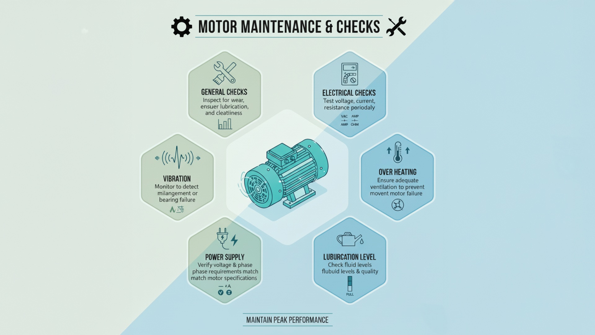
Motor Maintenance & Checks
General Checks- Check for wear, proper lubrication and that the motor is clean.
- Test voltage, current, and resistance periodically to ensure proper operation.
- Monitor vibrations to detect misalignment or bearing failure.
- Ensure adequate ventilation to prevent motor failure.
- Verify that the power supply meets the motor's voltage and phase requirements.
4. Centrifugal Pump Types & Configurations
Radial Flow Pumps
Fluid flows perpendicular to the impeller, ideal for high-pressure applications.
Axial Flow Pumps
Fluid flows parallel to the impeller, suited for high-flow, low-pressure applications.
Mixed Flow Pumps
Combination of radial and axial flow, offering a balance between pressure and flow rate.
Single-Stage Pumps
One impeller, used for low to moderate flow and pressure applications.
Multi-Stage Pumps
Multiple impellers, used for high-pressure applications.
Horizontal Centrifugal Pumps
Pump and motor are aligned horizontally, suitable for most industrial applications.
Vertical Centrifugal Pumps
Pump and motor are aligned vertically, used for space-saving applications.
Submersible Centrifugal Pumps
Pump and motor are submerged in the fluid, used for wastewater, sewage, irrigation and in boreholes.
Surface Centrifugal Pumps
Pump and motor are installed on the surface, used for water supply & irrigation systems, industrial processes, mining operations, oil and gas production.
Self-Priming Centrifugal Pumps
Can prime themselves, used for suction lift applications.
5. How Centrifugal Pumps Work
Fluid Entry
Fluid travels through the suction pipework and enters the pump through the suction nozzle. It then reaches the eye (the centre) of the impeller and is trapped between the impeller vanes.
Acceleration
The rotating impeller accelerates fluid outward from its centre to its outer diameter (centrifugal force). The fluid gains speed as it moves along the vanes of the impeller until it reaches its maximum velocity at the edge of the impeller, where it then enters the volute.
Energy addition
As the fluid's velocity increases, its kinetic energy also rises. The pump's impeller transfers mechanical energy from the motor to kinetic energy to the fluid, increasing its total energy. The energy transfer occurs as the fluid moves through the vanes, which are designed and angled to maximise the energy transfer.
Before we proceed, it's important to understand a fundamental aspect of a pump's operation: Bernoulli's principle. This principle states that:
As the velocity of a fluid (whether liquid or gas) increases, its pressure decreases, and vice versa. This occurs because the total energy of the fluid remains constant; as its kinetic energy (which is related to velocity) goes up, its potential energy (related to pressure) must decrease.
Think of it like this:
- when fluid moves slowly, its molecules are more densely packed, resulting in higher pressure.
- as fluid accelerates, its molecules spread out, reducing its density and resulting in lower pressure.
Pressure Reduction
According to Bernoulli's principle, as the fluid accelerates from the eye of the impeller, a low-pressure zone is created there and acts as a suction force, pulling more fluid into the pump (fluids travel from high pressure zones to low pressure zones). The difference in pressure between the low-pressure zone at the centre and the high-pressure zone at the outer edge helps push the fluid through the pump and into the discharge pipe.
Pressure Increase
The fluid's high kinetic energy is converted into pressure energy as the centrifugal and rotational velocities decrease (Bernoulli's principle).
Centrifugal Velocity: As fluid leaves the impellers edge and enters the volute at a high velocity, it slams into the internal casing wall of the volute. The liquids centrifugal velocity is abruptly stopped, and the velocity is converted to pressure.
Rotational Velocity: Due to the impeller spinning, there is rotary velocity. The fluid moves from the cut water around the increasing area of the volute and decelerates, decreasing the rotary velocity and converting to pressure.
Flow Generation
The higher-pressure fluid is then pushed through the volute and directed by the pumps casing toward the discharge nozzle. This increased pressure enables the fluid to be pumped to higher pressure areas, higher elevations or to distant locations.
Fluid Discharge
The accelerated fluid exits the pump through the discharge nozzle at discharge pressure. It enters the piping system at a higher pressure and flow rate than when it entered the pump and is now prepared to overcome the resistance in the system.
6. How to Select a Centrifugal Pump
When helping a customer select a centrifugal pump, asking the right systematic questions and following a process ensures they receive a pump that meets their needs.
General Questions
- What is the purpose of the pump?
- Is it to increase system pressure (booster pump)?
- Move fluid in a loop (circulation pump)?
- Extract water from deep underground (borehole pump)?
- Transfer water from a surface source (surface pump)?
- Drain water from a sump or pit (drainage pump)?
- Is this a replacement or new installation?
Replacements are usually easier as you can give the customer the same pump that they had or find a pump with similar specs. If they need a new pump because their system has changed or for a new installation, you will have to go through the whole question process.
New installations may give you the opportunity to recommend appropriate pipe sizes and piping designs and try minimise pipe length and bends in their system.
- What are the properties of the fluid?
When water is being pumped you should consider its temperature and quality.
- Temperature: Pumps with plastic impellers would not be able to handle hot water, so a pump with a brass or stainless-steel impeller should be used. Always ensure the fluid temperature is within the pump's specified range.
- Quality: pH level, turbidity, and solids presence impact the performance, durability, and maintenance of a pump. Selecting a pump with the right materials and design for these factors ensures efficient operation while reducing costs and downtime. For example, borehole pumps can only handle fluids with particles up to a certain diameter.
- What is the required:
- Flow rate? Determine the volume of fluid that needs to be pumped per unit time.
- Efficiency/energy consumption? Determine if energy savings and efficiency is a priority.
- Total dynamic head? Calculate the total head required to overcome resistance. It is important to know the fluid source height and the delivery points height. This information will help you determine the TDH of the system, which helps one determine the minimum head needed for the system for pump selection. More detailed information about this will be broken down in the TDH chapter.
- Are there:
- suction conditions to consider? Identify any suction lift/pressure requirements.
- installation constraints? Consider dimensions, mounting options, and accessibility.
- any standards or certifications required? Check for necessary certifications.
- budget or cost constraints? Establish financial limits.
- Automation requirements? Does the customer want any automation?
- What is the expected operating environment?
- Assess exposure to weather, vibration, or hazardous conditions.
- What power supply is available? And where is it?
Specific Applications
Borehole pump- The depth of the borehole, the water levels, the water yield from yield tests and the position and size of existing piping needs to be considered.
Yield tests provide insight into the volume of water available from the borehole at any given time. They are usually done by the company that drills the borehole. When selecting a borehole pump, you should only use 80% of the yield to keep the borehole from running dry and to allow it time to replenish, or it could be permanently damaged. If the yield test states that the yield is 50l/h, you will only consider (50 × 80% =) 40l/h.
Dewatering/Drainage pump- Depth and size of the sump, the distance from the sump to the exit point and the existing pipe size need to be considered to ensure proper flow rates and minimise friction losses.
7. Pump Nameplate Data & Specifications
A nameplate is used to identify a pump and show its operational requirements and capabilities. It provides an overview of the technical specifications and safety features of the pump. The specifications include information about the pump's performance, such as flow rate, head, power consumption, and duty ratings. This section aids in pump selection and helps users ensure the pump operates within its designed limits.
The safety information section includes features designed to protect the pump and user, such as overload protection, thermal safeguards, and ingress protection ratings. These help prevent damage from operational issues or environmental conditions.
Key information found on a pump nameplate:
Brand name & logo
This section usually has the company name and logo that manufactured the pump.
Model Number
Identifies the specific model of the equipment. Different manufacturers may use different nomenclature to classify their pump types. The letters typically indicate a specific series or design, while numbers could denote dimensions or other specific design features relevant to that model.
International Efficiency Class
The energy efficiency class indicates how efficiently the pump motor converts electrical energy into hydraulic energy. The efficiency classes are rated IE1 to IE5, with higher numbers having greater levels of efficiency. The classes help users select motors that will consume less energy and therefore reduce operating costs and lower the environmental impact.
IE2 and IE3 are the most common classes that centrifugal pump motors will have. IE3 motors are more advanced and provide greater energy savings and better performance. They are used in applications where high energy efficiency is critical, such as in systems with high running times or where energy savings are a major concern.
Certification Mark
The "CE" marking indicates that the pump complies with the Conformité Européenne (European Conformity) requirements, meaning that the product meets the essential requirements of relevant European health, safety, and environmental protection legislation. This certification is essential for market access within the European Union and provides assurance of the product's compliance with EU directives.
Flow rate
This specification tells you the range of how much fluid the pump can handle in a given time period.
Head
Indicates the head range of the pump measured in meters. It provides information about the pressure exerted by the pump and the pump's capability to lift the fluid to a certain height.
The head range helps in matching the pump to the requirements of a system and is used in conjunction with flow rate to select a pump that operates within the desired range.
Efficiency
"η (%)" Refers to the efficiency of the pump, expressed as a percentage.
This value indicates how effectively the pump converts the input power (or electrical energy) into hydraulic energy (or useful work) in moving the fluid.
If a nameplate states that a pump has an efficiency of 45%, it means that 45% of the electrical power supplied to the pump is converted into hydraulic energy, while the remaining 55% is lost, typically as heat and friction.
Power Output
P₂ represents the power output of the pump shown in horsepower (HP) or kilowatts (kW). It indicates the energy used by the pump during operation. This power output rating is crucial for selecting an appropriate motor for the pump and ensuring that the electrical system can handle the required power.
One horsepower is approximately 0.7457 kilowatts.
Power Input
The power input represents the amount of electrical power required to be consumed by the motor for it operate effectively. It is expressed in kilowatts (kW) or horsepower (HP) and is typically higher than the power output due to energy losses, such as heat and friction. Understanding this input power is crucial for calculating operational costs, assessing energy efficiency and ensuring the motor can handle the power input without risking overload or inefficiencies.
Minimum Efficiency Index
This is a metric used to indicate the energy efficiency of a pump in terms of its hydraulic performance at its best efficiency point (BEP) while considering energy losses. It states the MEI that the pump must meet or exceed to be considered efficient. The highest MEI value achievable is 0,7. The index is dimensionless and is expressed as a decimal.
Ingress Protection Rating
The IP rating indicates the level of protection provided by the pump's enclosure against the ingress of solid objects and liquids. It helps to determine how well the pump can withstand environmental factors such as dust, water, and other contaminants. Higher IP ratings imply better protection, leading to lower maintenance needs and longer service life. It is represented by the letters "IP" followed by two digits, each having a specific meaning.
Voltage
This provides information about the compatible electrical power supply that should be supplied to the pumps motor. Voltage ratings can also indicate whether the pump operates on a single-phase or three-phase electrical supply. Voltages between 120V-240V indicate a single-phase pump (1 ~) while ≥380V indicate a three-phase pump (3 ~).
Maximum liquid temperature
Refers to the maximum fluid temperature that the pump can safely pump without risking bearing damage, seal failure, overheating or degradation of the pump's components.
Class
The insulation class indicates the level of thermal insulation in the motor windings and the temperature range that the motor can operate safely within without overheating.
Amperage/Current
This indicates the amount of electrical current the motor requires and draws during operation. It is important that the electrical system is sized to handle the current demands. This helps in selecting appropriate protection devices and prevents issues such as overheating or electrical faults.
Dual amperage readings indicate Full load/No Load.
- Full Load: The maximum current drawn by the pump when operating at its rated capacity, speed, and pressure.
- No Load: The current drawn by the pump when operating at no load conditions, typically with the discharge valve closed or at minimum flow.
Frequency
Hz stands for Hertz, a unit of frequency used to measure the number of cycles per second of alternating current (AC) power. This indicates the frequency of the electrical supply that the pump's motor is designed to operate on. Different regions of the world use different standard frequencies for AC power (in South Africa, we use 50Hz).
Revolutions per minute
This refers to the rotational speed of the motor, which drives and sets the speed of rotation of the pump's shaft and impeller. It is measured in revolutions per minute (RPM). The rotational speed influences the flow rate and pressure with higher speeds increasing them and lower speeds decreasing them.
Weight
The weight indicated represents the pump's mass, which is important to plan for transportation, handling, installation and support structures. One must implement safe handling practices and use of the appropriate equipment to prevent accidents or damage. Additionally, the weight is used for shipping calculations, including packaging and transportation requirements.
Serial Number
N° stands for the serial number, which is a unique identifier assigned to each individual pump. It helps in tracking the pump's manufacturing history, warranty information and service records. It can also help with identifying and differentiating between pumps in large installations or for service and maintenance purposes.
Motor Details
This section provides motor details such as duty ratings and safety features.
Duty Ratings
Indicate the length of time a pump can operate reliably under certain conditions to ensure that the pump is used within its designed operating limits.
- S1 (Continuous Duty): Operates continuously at rated capacity without interruption. Ideal for non-stop applications.
- S2 (Short-Time Duty): Operates at rated capacity for a short period with required rest. Suitable for brief, intensive cycles.
- S3 (Intermittent Duty): Operates intermittently with rest periods. Designed for periodic use.
- S4 (Continuous Duty with Intermittent Loading): Operates continuously with varying loads. Suitable for applications with load fluctuations.
- S5 (Continuous Duty with Intermittent Loading and Starting): Operates continuously with variable loads and frequent starts/stops.
Safety Features
Safety features on a pump provide information about safety devices and mechanisms designed to protect the pump, motor, the surrounding environment and its operators.
- Overload Protection: Prevents damage from excessive load or current.
- Thermal Protection: Prevents overheating with sensors or indicators.
- Leak Detection: Alerts to leaks to minimise damage.
- High/Low Pressure Protection: Protects against abnormal pressure conditions.
- Dry Run Protection: Prevents operation without adequate fluid.
- Safety Shutdown: Automatically shuts down in case of critical failures.
These safety features are not only important for protecting equipment, but they also help prevent costly downtime, injuries, and system failures. When pumps and motors are running smoothly and safely, it ensures the longevity of the equipment, reduces the risk of accidents, and ultimately saves time and money in maintenance and repairs.
8. Pump Performance Curves (Characteristic Curves)
Pump curves are graphical representations of a pump's performance. A pumps technical data sheet will either have a full performance curve or have it deconstructed into the graphs on their own set of axes.
They show how the pump will perform under different conditions of flow rate. They are used to select the right pump for the requirements of a system, understand how changes in a system affect the pumps performance and to check if a pump is operating within its optimal range.
Performance curve
A performance curve is 3 curves relating to each other on a common graph. It tells you how much head/pressure a pump will produce at a certain flow rate, at a certain efficiency percentage and with what minimum head requirement. Sometimes it will include the power requirement (KW/HP) curve of the pump.
- Head-flow curve/s
- Efficiency curve
- Minimum head requirement curve (NPSHr)
Composite Pump Performance Curve
Pump manufacturers create "family curves" to make pump selection easier. These charts compare different models' performances or the same pumps performance, but with different impeller diameters or operation at different speeds. By comparing the head-flow curves on one chart, you can see how the different models, impeller sizes or speeds affect a pump's flow rate, pressure, and efficiency.
Head-Flow Curve
This curve plots the head that the pump produces against the flow rate. The head is plotted on the y-axis (vertical) and the flow rate is plotted on the x-axis (horizontal).
The red dot represents the shut off head/point, this is where the fluid has zero flow, but the head is at its maximum. This is because the pump generates the highest pressure when no flow is occurring.
The green dot represents the maximum flow point. As flow increases, the head decreases. This is due to fluid turbulence and because the pump must work harder to move fluid through the system which reduces the pressure that the pump can generate and the height that it can pump the fluid to.
The efficiency curve
The efficiency curve represents how efficiently a pump converts mechanical energy into hydraulic energy at various flow rates. It plots the pump's efficiency as a percentage. When efficiency is placed on its own axes, the x-axis of the curve represents the flow rate, while the y-axis represents the efficiency percentage.
The best efficiency point (BEP) of a pump is usually around ¾ of the curve - the closer the pump operates to the BEP, the more efficient it will be.
Curve Shapes
The efficiency curve is often a bell-shaped curve. Efficiency increases as the flow rate increases, peaks at the BEP, and then decreases as the flow rate continues to increase.
For many curves, the efficiency may be at the highest point (purple point), but it is too far right of the curve. Always try ensuring that the pump operates closest to the BEP, as its best efficiency is not always at the highest point on the efficiency curve. This is where it may sit in the ¾ range.
Maximise pump efficiency by aligning the operating point with the Best Efficiency Point (BEP). Consider system requirements and adjust pump speed or impeller size accordingly. Be mindful of changing system conditions that may affect efficiency. Efficiency curves guide informed pump selection as by matching your pump well to your system can reduce operational costs, enhance system reliability and extend pumps lifespan while minimising maintenance.
Operating "too right" or "too left" of the curve
When one operates a pump away from the BEP, it is described as operating the pump "too left" or "too right" of the curve.
"Too Left" Issues:
- Reduced Efficiency: Operating at very low flow rates reduces pump efficiency, resulting in higher energy consumption for each unit of water pumped.
- Increased Risk of Overheating: Low flow rates may not provide adequate flow for proper cooling, increasing the risk of overheating and damage to the pump.
- Potential for Short-Cycling: At low flow rates, pumps may experience short-cycling, where they frequently start and stop, leading to wear and damage.
- Reduced System Performance: Insufficient water flow can impair the performance of the system.
- Pump Cavitation: Very low flow rates can cause cavitation issues if the pump isn't designed for such conditions, causing damage and decreased efficiency.
"Too Right" Issues:
- Reduced Efficiency: Operating at higher flow rates than the BEP decreases pump efficiency, as more energy is needed to move the same amount of water.
- Increased Power Consumption: Higher flow rates result in greater power consumption, leading to higher operational costs.
- Excessive Vibration and Noise: High flow conditions can cause excessive vibration and noise due to turbulence and potential cavitation.
- Cavitation Risk: High flow rates increase the risk of cavitation, which can damage the pump over time.
- Wear and Tear: Operating at high flow rates puts more stress on the pump components, accelerating wear and potentially leading to faster degradation.
The NPSH Curve
The NPSH (Net Positive Suction Head) curve plots the minimum suction head (NPSHr) condition required at a certain flow rate in order to prevent cavitation. The NPSHr is shown on the vertical y-axis usually in meters, and the flow rate on the horizontal x-axis.
The available NPSH (NPSHa) is the net positive suction head available at the pumps suction inlet. The head available at the pump's inlet must never be less than the required head as this is when cavitation occurs.
NPSHa > NPSHr
For systems where flow rates vary, review how NPSHr changes with flow to ensure adequate NPSH is available across the entire operating range to maintain the pumps performance, reduce maintenance needs and extend its operational life.
Curve Shapes
The curve generally rises as the flow rate increases. High flow rates mean that the pump may have increased losses due to friction and turbulence in the pump and piping. This can lead to the pump requiring more suction head to overcome these losses, resulting in an increased NPSHr at high flow rates.
The curve can also be raised at low flow rates due to the fluid having less kinetic energy, and the effects of turbulence and flow separation becoming more pronounced. This results in the fluid having higher friction losses within the pump and inlet, leading to a higher NPSHr.
Cavitation
Cavitation is a significant concern in pump operations and estimates suggest that it accounts for approximately 20% to 40% of all pump failures. Often, we say that a pump cavitates, but a pump actually 'experiences' or 'suffers' from cavitation, as it is a poorly designed system that causes cavitation.
Cavitation is a phenomenon that occurs in liquids when pressure drops significantly, leading to the formation of vapour bubbles. To understand it better, we can compare it to the process of boiling water and the creation of steam.
When water is heated, energy is added to the molecules, and they start to move faster. Remember Bernoulli's principle? As it starts to reach its boiling point, the fluid accelerates, its molecules spread out and reduce the fluids density, resulting in it having a lower pressure. When the pressure drops to the atmospheric pressure, it will start to boil, and steam (water vapour) will start to flow off the top.
However, with cavitation, the situation is quite different: instead of a controlled boiling process, the pressure of the area that the liquid is in drops, allowing vapor bubbles to form. These bubbles are akin to the steam produced during boiling but occur under low-pressure conditions within a pump.
As these vapour bubbles move to areas of higher pressure, they are compressed and implode violently, creating shock waves that can erode metal surfaces and cause damage to the pump components. This destructive collapse contrasts sharply with the harmless release of steam during boiling.
The presence of air disrupts the flow of fluid and causes instability. Cavitation leads to reduced efficiency, performance and lifespan of the pump and increases maintenance needs. The shockwaves cause wear and damage to the pumps components as well as erosion, noise, vibration, and potential failure of the pump over time.
In summary, cavitation is the formation and collapse (implosion) of vapor bubbles in a fluid, caused by a rapid change in pressure, generating shock waves that can lead to erosion or pitting of surfaces in the pump and pipework.
| Type of Cavitation | Flow Behaviour | Cause |
|---|---|---|
| Vaporisation | Occurs when liquid pressure drops below its vapor pressure, forming vapor bubbles, typically in low-pressure areas like the impeller. When pressure increases the vapor bubbles collapse, creating shockwaves. | Is the result of inadequate NPSHa (such as a strangled valve, clogged filter or inadequate submergence). |
| Internal Re-Circulation | Occurs when there are low flow conditions (restricted discharge flow), forcing fluid to recirculate within the pump. This causes fluid heating, vapor bubble formation, and collapse, typically near the impeller or volute where flow direction or velocity changes abruptly. | It results from the discharge side from a strangled valve, clogged filter, over-pressurised header or check-valve installed backwards. |
| Vane Pass Syndrome | When the blade tips at the outside diameter of the impeller are passing too close to the cut water of the pump casing which leads to low-pressure zones which cause vapor bubbles to form collapse and create shockwaves. | An oversized impeller, coating the internal casing, repaired or rebuilt with incorrect parts and measurements. |
| Air Aspiration | Air aspiration cavitation happens when air or gas is drawn into and mixed with a liquid flow via leaks or openings, creating bubbles when pressure drops. | Operation too right of BEP, improper suction pipe, excessive turbulence, fluid flow too fast, inadequate flange torque, insufficient sealing. |
| Turbulence | Turbulence cavitation occurs when chaotic and irregular fluid flow causes rapid changes in velocity and pressure and creates localised low-pressure areas leading to the formation and collapse of vapor bubbles which can erode and damage surfaces and components and reduce efficiency. This typically happens at high flow velocities or around obstacles, such as bends or impeller blades. | Caused by poor system design and inappropriate suction system design (vessel, piping, connections, fittings) |
9. Friction Graphs
Friction (loss) graphs show how much head is lost due to friction as fluid flows through pipes, fittings, and other components in a system.
It is used to estimate head loss due to friction, ensuring the system is properly designed to maintain flow in pipeline design. Additionally, it aids in diagnosing issues related to high friction losses that affect system performance.
The flow rate (Q) is plotted on the horizontal (x) axis and the friction losses are plotted on the vertical (y) axis. The horizontal lines show how friction loss varies with flow rate, speed and pipe diameter and the vertical lines show the flow rate. The upward diagonal lines plot the internal diameter of the piping, and the downward horizontal lines plot the speed of the fluid.
Take note that this is the friction loss graph for cast iron piping. Different piping materials will have differing friction losses in fluids flowing through them. Their internal walls will have differing roughness's, and a rougher surface will create more turbulence and additional resistance to flow, which increases friction loss.
| Friction Losses in Accessories: Equivalent Length of Straight Piping in Meters | |||||||||||||||||
|---|---|---|---|---|---|---|---|---|---|---|---|---|---|---|---|---|---|
| Pipe Diameter | 25 | 32 | 40 | 50 | 65 | 80 | 100 | 125 | 150 | 200 | 250 | 300 | 350 | 400 | 500 | 600 | 700 |
| Curve 90° | 0.2 | 0.3 | 0.4 | 0.5 | 0.7 | 1 | 1.2 | 1.8 | 2 | 3 | 5 | 5 | 6 | 7 | 8 | 14 | 16 |
| Elbow 90° | 0.3 | 0.4 | 0.6 | 0.7 | 0.9 | 1.3 | 1.7 | 2.5 | 2.7 | 4 | 5.5 | 7 | 8.5 | 9.5 | 11 | 19 | 22 |
| Diffuser cone | 5 | 5 | 5 | 5 | 5 | 5 | 5 | 5 | 5 | 5 | 5 | 5 | 5 | 5 | 5 | 5 | 5 |
| Foot valve | 6 | 7 | 8 | 9 | 10 | 12 | 15 | 20 | 25 | 30 | 40 | 45 | 55 | 60 | 75 | 90 | 100 |
| Stop valve | 4 | 5 | 6 | 7 | 8 | 9 | 10 | 15 | 20 | 25 | 30 | 35 | 40 | 50 | 60 | 75 | 85 |
| Gate valve open | 0.5 | 0.5 | 0.5 | 0.5 | 0.5 | 0.5 | 1 | 1 | 1.5 | 2 | 2 | 2 | 2.5 | 3 | 3.5 | 4 | 5 |
| Gate valve ¾ open | 2 | 2 | 2 | 2 | 2 | 2 | 4 | 4 | 6 | 8 | 8 | 8 | 10 | 12 | 14 | 16 | 20 |
| Gate valve ½ open | 15 | 15 | 15 | 15 | 15 | 15 | 30 | 30 | 45 | 60 | 60 | 60 | 75 | 90 | 105 | 120 | 150 |
Head losses in pipes
Head loss refers to the loss of pressure in a system due to friction and other factors as the fluid moves through pipes, fittings, and components. It is measured in meters and affects the overall efficiency of the pumping system.
- Friction Loss: This is the resistance that fluid encounters when flowing through pipes, caused by the pipe's diameter, material, roughness and by the fluid's velocity and viscosity.
- Static Head Loss: This occurs due to elevation differences in the system, such as when water must be pumped up vertically. It includes the vertical distance from the source to the pump (static suction lift) -if there is- and the vertical distance from the pump to the discharge point (static discharge head).
- Dynamic Head Loss: This includes losses due to changes in velocity, such as those caused by fittings, bends, and valves in the piping system.
10. Total Dynamic Head (TDH) Explained
10.1. Overview
Total Dynamic Head (TDH) is used for pump selection. It calculates the total energy needed to move fluid through a pipeline, considering factors like friction, elevation, velocity and pressure, which directly influence your flow. Calculating accurately can mitigate the risk of the pump being inadequate and trying to cover the losses, which will eventually make it over work, overheat and eventually burn out. In essence, TDH is used to design reliable, cost-effective, and efficient fluid transfer systems.
TDH considers these factors:
- Static Head (Hs): Is the change in elevation of the liquid across the system. If the vessel on the suction side is on the same level as the discharge, Hs=0.
- Pressure Head (Hp): Is the change of pressure across the system. If there is no change in pressure, such as when both vessels are exposed to atmospheric pressure, Hp=0.
- Velocity Head (Hv): The energy lost in the system due to the velocity changes of the liquid flowing through the pipes.
- Friction head (Hf): The friction losses in the system.
TDH = Hs + Hp + Hv + Hf
TDH = Hs + (Δpsi × 2.31)/sp.gr + v²/2g + Hf
Where:
- Δpsi = The difference in pressure in the system. (Δpsi = P1-P2)
- sp.gr = Specific gravity of the fluid, for water the value is 1.
- v = The velocity of the fluid.
- g = Acceleration due to gravity, which is approximately 9.81m/s².
10.2. Suction Conditions
Hs for Flooded Suction
A flooded suction scenario occurs when a pump receives fluid from a higher elevation or with pressure.
To find the Static Head (orange arrow), you must subtract the elevation of the fluid source (blue arrow) from the elevation of the discharged fluid (purple arrow).
Hs for Suction lift
A suction lift scenario occurs when a pump draws fluid from a lower elevation, overcoming gravity to lift the fluid to the pump's suction inlet.
To find the static head (orange arrow), you must add the height between the fluid source and the pumps suction (blue arrow) and the height between the pump and discharged fluid (purple arrow).
The maximum depth that you should have suction lift is around 9m (however, this depth may vary depending on the atmospheric pressure in the area of installation), as deeper than that will cause the weight of the water and its gravity to compete and cause the fluid to start boiling and vaporising in the piping.
The head that is calculated from TDH is the head required by the system according to the customers criteria. If a pump that cannot provide enough head for the systems requirements is selected, it can lead to insufficient flow rate, increased energy consumption and excessive operational costs.
10.3. Applications
Scenario 1: Emptying a Pit (Submersible-Drainage)
A customer would like to drain a sump that fills up weekly for a grey water system. It is 3x 3,3m and 1m deep. They would like to use the water for irrigation for their garden but want the water pumped into their 1m high 10 000L break tank first. They say that the water is 15°C and has suspended solids with a maximum diameter of 5mm. They would like to empty the sump within 2 hours and for the pump to automatically stop.
Solution Process:
- Is this a new installation or replacement? This is a new installation.
- What is the purpose of the pump? To empty a sump of water, they will need a dewatering/drainage pump.
- What are the properties of the fluid?
- Temperature: 15°C
- Quality: There solids present are 5mm in diameter.
- Depth and size of the sump?
The depth of the sump is 1m and is about 3m by 3,3m. This information is used to calculate the volume of the sump:
Volume = l × b × h
Volume = 3 × 3,3 × 1
Volume = 9,9m³ - What is the required:
- Flow rate? The customer would like the sump drained in 2 hours.
9,9m³ per 2 hours = 4,95m³ per 1 hour (4,95m³/h) - Efficiency/energy consumption? Is not a priority in this scenario.
- Total Dynamic Head? Using TDH = Hs + Hp + Hv + Hf
- Flow rate? The customer would like the sump drained in 2 hours.
TDH Calculation:
Static head: The depth of the sump is 1m and this customers 10 000L tank a meter high. When the sump is full of water, the fluid has more pressure and energy when entering the pump, but when there is less water, the pump must add more energy to the fluid to meet the same requirement, this is why we calculate the TDH with the total elevation when draining a sump. In this scenario, the static head will be 2m.
Pressure head: Both vessels are exposed to atmospheric pressure, meaning that the pressure head will be equal to 0.
Velocity head: Using friction graphs to find and recommend what size of piping the customer will need. The velocity of the fluid running at a flow rate of 4,95m³/h through 40mm piping is around 1,1m/s.
Friction Head: The friction losses at 4,95m³/h flow and 40mm diameter pipe is around 4m per 100m. There is 8,3m of piping in total (including equivalent length for fittings). This gives 0,33m of head loss. Adding the safety factor of 5m makes the total friction loss 5,33m.
TDH = 2 + 0 + 0,06 + 5,33 = 7,39m
A submersible drainage pump that can deliver 7,39m of head at 4,95m³/h is needed.
Scenario 2: Replacement Surface Pump
A customer needs a replacement pump that can deliver 2,2 bar at 3m³/h. The water being pumped has already gone through a filter system and is at ambient temperature. They installed 50mm piping and a pump cover for their previous pump installation.
After going through the selection process, the CM100V meets the requirements, providing 24,1m of head at 4,2m³/h (exceeds the needs by 2 meters/0,2 bar) with 40% efficiency.
Scenario 3: New Surface Installation
A customer would like to pump water from a tank on one side of their property to a tank on the other, near their home. They say that there is an incline of about 20m across their property. The tank is raised 2m off the ground and the tank near their home is a 20 000L. They already have 65mm piping installed. Their piping length is 49m.
- What is the purpose of the pump?
This installation will need a surface pump. - Is this a replacement or new installation?
This is a new installation. - What are the properties of the fluid?
- Temperature: Ambient temperature.
- Quality: White water.
- What is the required:
- Flow rate? They would like a flow rate of 10m³/h.
- Efficiency/energy consumption? Energy efficiency is not a priority in this example.
- Total dynamic head? We need to use the formula TDH = Hs + Hp + Hv + Hf to calculate the total head required to overcome resistance in the system.
Static Head
A 20 000L tank is 3,6m high, which we will round off to 4m (can only be done for the discharge side). The water also needs to be pumped up a 20m incline. The tank on the suction side is raised 2m, so this is a flooded suction scenario. The static head will therefore be:
Static Head = 20 + 4 - 2 = 22m
Pressure Head
Neither vessel is pressurised, they are exposed to atmospheric pressure.
Velocity Head
To find the velocity of the fluid, we can use friction graphs to find and recommend what size of piping the customer will need and find the velocity of the fluid. The velocity of the fluid running at a flow rate of 10m³/h through 65mm piping is around 0,8m/s.
Friction Head
The friction losses at 10m³/h flow and 65mm diameter pipe is around 2,6m per 100m. There is 49m of piping and there are 3 elbows (one is a 45° elbow, but our table does not account for them, so we will use the 90° value) and 1 gate valve in our system. The piping and fittings make the total piping length (49 + (0,9 × 3) + 0,5 =) 52,2m.
This means that there is 0,53m of head loss for 52,2m of piping. Adding the safety factor of 5m makes your total friction loss 5,83m.
Calculating TDH
TDH = Hs + Hp + Hv + Hf
TDH = 22 + (0 × 2.31) / 1 + (0,8)² / (2 × 9,81) + 5,83
TDH = 22 + 0 + 0,03 + 5,83 = 27,86m
A surface pump that can deliver 27,86m of head at 10m³/h is needed. This head value is the minimum necessary for the fluid to reach the tank, so we can make the head value between 30–40m so that the fluid flowing into the tank near the customer’s home will have more pressure.
- Are there:
- Suction conditions to consider? The delivery vessel is raised 2m off the ground.
- Installation constraints? There are no installation constraints in this example.
- Any standards or certifications required? There are no certifications needed for this installation.
- Budget or cost constraints? There is no financial limit for this installation.
- Automation requirements? The customer would like the pump to run at the same time every day for an hour. This is where a control panel with a timer will be used.
- What is the expected operating environment?
- The pump will be kept in a pump box.
- Single phase and three phase power supply is available. If this is the case, suggest a three-phase pump as it uses less amperage and can lead to energy savings.
Pump Selection
Now that we have all the necessary information, we can start comparing models and makes. The MB200 has the description:
“Two impeller compact centrifugal pump for constructing pressurisation systems for civil and industrial plant: guaranteed good ratio between pressure and flow rate.”
Let’s look at its family curve. The minimum head needed is plotted on the graph, however we want a head between 30 and 40m, so the MB150 will not be considered, even though it meets our (minimum) system requirement. The MB200 will be the better selection, and looking at the efficiency, it has over a 50% efficiency at that flow rate.
Looking at the duty table, we can see that the head at 10m³/h is between 30,8 and 35,2m, which meets our system requirements. This is where we can also see the difference in the current draw between the three phase and single phase. It would be best to suggest the MBT200.
The water that the pump will be transporting is white water and of ambient temperature, meaning that we can suggest this pump with a Noryl® impeller.
Wrongful pump selection can lead to pump and system failures, safety hazards, and significant financial losses. Incorrectly chosen pumps can cause overheating, vibration, and premature wear, resulting in reduced lifespan and increased maintenance costs. In worst-case scenarios, faulty pumps can lead to explosions, chemical spills, or release of hazardous materials, putting workers’ lives at risk. It can also lead to environmental damage, regulatory non-compliance, and costly lawsuits.
Workers involved in pump selection may be held liable for negligence or failure to follow established procedures, resulting in disciplinary actions or even criminal prosecution.
Common scenarios of wrongful pump selection include:
- Inadequate flow rate or pressure handling
- Incompatible materials or corrosion resistance
- Insufficient power or motor overload
- Incorrect pump type or configuration
- Failure to consider operating conditions (temperature, viscosity, etc.)
11. Centrifugal Pump Installation Guide
Proper installation is important for the safe and efficient operation of a water transfer system. A well-installed pump assures optimal performance, minimises the risk of equipment failure, and reduces maintenance requirements. Before starting the installation process, carefully plan and prepare the site, select the correct piping and fittings, and follow the manufacturer’s instructions for a successful and trouble-free installation.
11.1. Pre-installation Checks
- Ensure the installation site is clean, level, and adequately prepared, with easy access for maintenance.
- Verify the pump’s suitability for the application by checking its flow rate, pressure, fluid compatibility, and piping system.
- Confirm the pump's power requirements and ensure it matches the available power supply.
11.2. Installation Steps
11.2.1. Surface Pumps
- Securely mount the pump to a level, stable base using anchor bolts or a mounting plate.
- Connect suction and discharge piping to the pump, ensure proper alignment and tightening. Provide adequate support for the piping to prevent strain on the pump.
- Install valves and fittings as required.
- Connect the motor to the power supply, following the manufacturer’s guidelines for wiring and electrical connections.
- Install and calibrate control systems (pressure switches, flow meters) for monitoring and managing pump operation.
- Vent and prime the pump to prevent airlocks and ensure smooth operation.
- Perform initial testing to ensure proper pump operation, flow rate, and pressure.
11.2.2. Submersible Pumps
- Ensure the well or pit is clear of debris and sediment.
- Lower the pump into the well or pit, ensure it is level, properly aligned, and mounted or anchored to prevent floating or shifting.
- Connect suction and discharge pipes to the pump, ensuring proper alignment, fittings, and tightening. Provide adequate support for the piping to prevent strain on the pump.
- Install valves and fittings as required for the application.
- Connect the motor to the power supply, following the manufacturer’s guidelines for wiring, sealing, and electrical connections.
- Install and calibrate control systems for monitoring and managing pump operation.
- Perform initial testing to ensure proper pump operation, flow rate, and pressure.
11.3. Post-installation Checks
- Verify proper pump operation and performance.
- Check for leaks, vibrations, or unusual noises.
- Ensure proper electrical connections and motor operation.
- Test control systems and safety features (e.g., overpressure protection).
11.4. Additional Considerations
- Follow manufacturer’s instructions for specific installation requirements.
- Ensure proper grounding and bonding for electrical safety.
- Consider installing a pump protection system.
- Regularly inspect and maintain the pump and surrounding equipment.
11.5. Priming
Priming a water pump is essential to ensure it operates effectively and avoids damage. Here is a step-by-step guide on how to do it:
- Ensure the pump is turned off and inspect the pump and piping for any leaks.
- Locate the priming port (threaded opening at the top or side of the pump or can be integrated with the suction inlet) and open it by unscrewing or removing the plug or cap.
- Pour water into the priming port until the pump chamber and suction line are filled with water, ensure there are no air pockets.
- Seal the priming port once the pump is filled with water.
- Turn the pump on and ensure it is operating smoothly, that water is flowing from the discharge side, and that there are no leaks.
Remember to always follow manufacturer’s instructions as the priming process can vary, and always use clean water to avoid clogging the pump with debris.
12. Centrifugal Pump Maintenance & Troubleshooting
12.1. Maintenance
Routine maintenance on centrifugal pumps is vital for several reasons. It helps identify problems early and prevent unexpected failures, thus avoiding costly repairs and minimising downtime. It also ensures safety and compliance with industry regulations. Regular upkeep ensures the pump performs optimally, maintaining flow, pressure, and efficiency. Proper maintenance will help you make sure that your pump operates at its optimal performance, extending its lifespan and reducing energy consumption.
The maintenance programme for centrifugal pumps is categorised into three types: Routine, Quarterly, and Yearly.
12.1.1. Routine Maintenance
12.1.2. Quarterly Maintenance
12.1.3. Annual Maintenance
Remember to always refer to the operation handbook and follow the manufacturer’s recommendations for maintenance and replacement parts.
Additional Intervals:
- Every 2–5 years: Replace wear rings, seals, and bearings as needed.
- Every 5–10 years: Consider replacing the pump's impeller and shaft.
12.2. Common Issues and Solutions
12.2.1. Zero Flow After Startup
| Possible Causes | Description | Solutions | Addressing the Problem |
|---|---|---|---|
| Clogged Suction Strainer | A blockage preventing fluid from entering the pump. | Check and Clean | Inspect and clean the suction strainer or filter. |
| Closed Discharge Valve | The valve is not fully open, restricting flow. | Open Valve | Ensure the discharge valve is fully open. |
| Air Lock | Air trapped in the pump or system, preventing fluid movement. | Bleed Air | Use air release valves or vents to remove trapped air. |
| Pump Not Primed | The pump casing is not filled with fluid, leading to no flow. | Prime the Pump | Follow the manufacturer’s instructions to prime the pump. |
12.2.2. Flow Decreases or None at All
| Possible Causes | Description | Solutions | Addressing the Problem |
|---|---|---|---|
| Cavitation | Formation of vapour bubbles in the pump due to inadequate NPSH. | Address Cavitation | Improve NPSH (reduce suction lift and/or increase pump speed and pressure). |
| Wear and Tear | Erosion or damage to the impeller or other components. | Inspect Components | Check and replace worn or damaged parts. |
| System Blockage | Blockages or restrictions in the piping or valves. | Clear Blockages | Inspect and clear any obstructions in piping. |
| Incorrect Pump Speed | The pump may not be operating at the required speed. | Adjust Speed | Verify and adjust the pump speed as needed. |
12.2.3. Overloaded Driver
| Possible Causes | Description | Solutions | Addressing the Problem |
|---|---|---|---|
| Increased System Resistance | Higher-than-expected system pressure or resistance. | Check System Resistance | Verify that the system pressure and resistance are within the pump’s design specifications. |
| Improper Motor Size | The motor may be undersized for the pump. | Verify Motor Size | Ensure the motor is sized for the pump’s requirements. |
| Pump Misalignment | Misalignment of shaft(s) can cause excess load. | Align Shafts | Realign pump and motor shafts to reduce mechanical load. |
| Blockage or Restrictions | Blockages in the system or pump can cause increased load. | Clear Blockages | Inspect and remove any blockages or restrictions. |
12.2.4. Bearings Overheating
| Possible Causes | Description | Solutions | Addressing the Problem |
|---|---|---|---|
| Lack of Lubrication | Insufficient or contaminated lubricant. | Lubricate Bearings | Check, replenish, or replace the lubricant as needed. |
| Misalignment | Misalignment of the shaft(s) can cause excessive friction. | Align Components | Ensure proper alignment of the pump and motor shafts. |
| Overloading | Excessive load or pressure on the pump. | Reduce Load | Check for and correct any overloading conditions. |
| Contamination | Dirt or debris entering the bearing assembly. | Clean Bearings | Inspect and clean bearings and replace if necessary. |
12.2.5. Vibration
| Possible Causes | Description | Solutions | Addressing the Problem |
|---|---|---|---|
| Imbalance | Imbalance in the rotating parts, such as the impeller. | Balance Rotating Parts | Check and correct imbalance in the impeller or rotating components. |
| Misalignment | Misalignment of the pump and motor shafts. | Align Shafts | Ensure proper alignment of the pump and motor shafts. |
| Worn Bearings | Worn or damaged bearings causing excessive movement. | Replace Bearings | Inspect and replace worn bearings as needed. |
| Piping Issues | Pipe supports or anchors may be loose or improperly installed. | Inspect Piping | Check and secure pipe supports and anchors to reduce vibration. |
12.2.6. High Noise Level
| Possible Causes | Description | Solutions | Addressing the Problem |
|---|---|---|---|
| Cavitation | Cavitation can cause noise due to vapour bubbles collapsing. | Address Cavitation | Improve NPSH, reduce pump speed, or adjust system parameters to resolve cavitation issues. |
| Imbalance | Imbalance in the impeller or other rotating components. | Balance Rotating Parts | Correct any imbalance in rotating components. |
| Loose Components | Loose or improperly secured components may create noise. | Secure Components | Tighten and secure any loose parts or components. |
| Air in System | Air trapped in the pump or piping can cause unusual noises. | Bleed Air | Use air release valves or bleed points to remove trapped air. |
By identifying and addressing these common problems, you can ensure your centrifugal pump operates efficiently and reliably. Regular maintenance and timely troubleshooting are key to preventing issues and maintaining optimal pump performance.
13. Basic Principles and Definitions
Abrasive Fluids
Contain solid particles that can erode pump materials over time.
Ambient Temperature
When water reaches the same temperature as the surrounding environment.
Calibration
The process of verifying and adjusting the pump's performance to ensure accuracy and reliability.
Cut Water
Cut water refers to the point where the pump's flow is directed away from the impeller into the discharge pipe.
Corrosion
The degradation or deterioration of pump materials (particularly metals), due to chemical reactions with water or other substances.
Density
A physical property that describes the amount of mass contained in a given volume of a substance.
Discharge
The exit point of the fluid from the pump. It is where the pressurised fluid is released into the piping system for distribution or use.
Dry Running
When a pump operates without fluid or sufficient liquid to cool its internal components.
Dynamic Head
The total head, including both static head and head losses due to friction and turbulence. It is essential for calculating the required pump head and system performance.
Efficiency (η)
How well a pump converts the input energy (total power input) into useful hydraulic energy (useful power output). It is defined as the ratio of hydraulic power output to the mechanical power input.
Efficiency Formula: Efficiency (%) = (Useful Hydraulic Energy / Input Energy) × 100
- Input Energy: This is the energy supplied to the pump from an electric motor. It is the total energy used to operate the pump (measured in watts (W) or horsepower (Hp)).
- Useful Hydraulic Energy: This is the energy the pump transfers to the fluid to move it (calculated as Q × H × Fluid Density × g).
If a pump is 80% efficient, it means that 80% of the energy supplied to the pump is used effectively to move the fluid, while the remaining 20% is lost as heat or friction.
Erosion
The wear or removal of pump materials (particularly metals), due to fluid flow, particles, or cavitation.
Flow Rate (Q)
Flow rate measures how much fluid passes through a specific point in a system over a given period of time. It is critical for sizing pumps and ensuring they meet the demands of a system.
The volume of fluid passing through a pump, pipe, or system per unit time is measured in litres per second (L/s) or cubic metres per hour (m³/h).
For instance, if a pipe has a flow rate of 10 litres per second, that means 10 litres of fluid are moving through the pipe every second.
Frequency
Frequency measures the number of oscillations of current per second, expressed in Hertz (Hz). 50Hz systems tend to consume less power and have fewer harmonics, reducing electromagnetic interference. It is used in Europe, Asia, Australia, and Africa. 60Hz is used mostly in North and South America, Japan, and Taiwan.
Full Load Current
The maximum current drawn by the pump's electric motor when operating at its rated capacity, speed, and pressure.
Head (H)
Head is the height to which a pump can raise a fluid against gravity. It represents the energy imparted to the fluid and is expressed in units of height (m). It helps determine the pump’s ability to overcome system resistance and deliver fluid to the desired location.
Inlet
The entry point of the fluid into the pump.
Lubricant
A substance, such as oil or grease, used to reduce friction and wear between moving parts in the pump.
Net Positive Suction Head (NPSH)
NPSH stands for Net Positive Suction Head. It is a measure used to ensure that a pump can operate effectively without experiencing cavitation.
To make sure that a pump will not experience cavitation, there are two values of NPSH that we need to know — the available NPSH (NPSHa) and the required NPSH (NPSHr).
- Net Positive Suction Head Available (NPSHa): This is the pressure available at the pump’s suction. It is determined by the system and is calculated by considering factors like the pressure in the suction tank, atmospheric pressure, and the height of the fluid above the pump. It is the pressure available to prevent the fluid from vaporising before it enters the pump.
- Net Positive Suction Head Required (NPSHr): This is the minimum pressure needed at the pump’s suction to keep the pump from cavitating. It is determined by the pump manufacturer and varies depending on the pump design and operating conditions.
If the NPSHa (what you have) is less than the NPSHr (what you need), the pump may cavitate.
Overload
When a pump is subjected to excessive stress beyond its designed capacity, resulting in potential damage or failure.
Phases
- Single-Phase Electrical Supply: Consists of two wires (hot and neutral) that provide a single AC voltage.
- Three-Phase Electrical Supply: Consists of three or four wires (three hot and one neutral) that provide three AC voltages (phase-shifted by 120 degrees).
Pressure (P)
Pressure is a measure of how much force is applied by the fluid per unit area, measured in pascals (Pa), bars, or pounds per square inch (psi). Pressure helps us evaluate the pump's performance and its ability to move fluid against system resistance.
In simpler terms, pressure is like pushing on a surface. If you push harder (more force) or push on a smaller area, the pressure increases. Conversely, if you push with the same force but over a larger area, the pressure decreases.
For example, if you press your finger against a balloon, the pressure you apply is the force of your finger divided by the area of contact with the balloon.
Priming
The process of filling the pump casing with fluid to eliminate air for the pump to create suction.
Shaft Misalignment
Shaft misalignment occurs when the pump shaft is not properly aligned with the motor shaft or other connected components and can lead to increased vibration, wear, and pump failure.
Shroud
Component of the impeller that adds a protective barrier and structural support to the impeller blades and helps reduce turbulence.
Slurries
A mixture of solids and a liquid, consisting of fine particles suspended in the fluid. They can be abrasive and cause wear and damage to pump components.
Static Head
The vertical distance between the liquid surface and the highest point in the system (discharge point). Static head helps determine the minimum head requirement for a pump to lift the fluid.
Suction
Refers to the process of drawing fluid into the pump from the source.
Suction Head
Suction head is the vertical distance between the surface of the liquid being pumped and the pump’s inlet. Proper suction head is necessary to maintain efficient pump operation and avoid cavitation.
Suspended Solids
Particles that remain distributed throughout a fluid and do not settle at the bottom.
Technical Data Sheet
A document that provides detailed information about a centrifugal pump's specifications, performance curves, installation requirements, and dimensions.
Torque
Torque is a measure of the rotational force produced by the motor. It is essential for both starting and maintaining the pump's operation.
Starting Torque: The amount of torque generated when the motor starts from a standstill. It needs to be sufficient to overcome the inertia of the pump and any load it may be carrying to prevent stalling.
Running Torque: The torque required to keep the motor operating at a desired speed once it has started. This torque must be sustained to ensure consistent pump performance under varying conditions.
Imagine using a wrench to tighten a bolt; the torque is the turning force you apply to the wrench handle. It is calculated by multiplying the force you use by how far from the bolt you are applying it (distance from the rotation point). The further you are from the bolt, the more torque you create, making it easier to turn.
Transducer
A device that converts one form of energy into another to provide feedback on the operating conditions of a system or provide control signals to the VSD system. They are typically used to measure physical parameters such as speed, pressure, temperature, or flow.
Turbulence
Refers to the chaotic and irregular flow of fluid, which can occur at high flow rates.
Vessel
Any container or tank that holds fluid.
Viscosity
The measure of a fluid’s resistance to flow, affecting pump performance and efficiency.
Water Hammer
(Hydraulic shock) A sudden, high-pressure surge that occurs in a fluid system, typically in pipes, due to sudden valve closure, abrupt starts or stops, air locks, and sharp bends, tees, or dead ends.