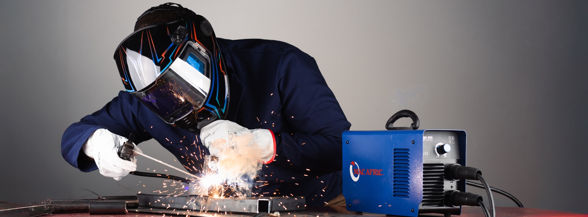
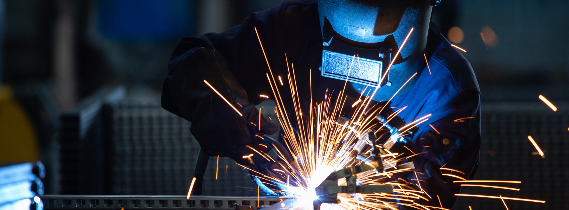
Welding Safety and Technical Guide
Listen to a podcast about this article
WELDING SAFETY AND TECHNICAL GUIDE
WELDING SAFETY CHECKLIST
Electric Shock Can Kill You
Hazard Severity Factors:
- Wetness
- Welder in or on workpiece
- Confined space
- Electrode holder and cable insulation
Precaution Summary:
- Insulate welder from workpiece and ground using dry insulation, rubber mat or dry wood
- Wear dry, hole-free gloves (change if damaged)
- Do not touch electrically "hot" parts or electrode with bare skin or wet clothing
- If wet area and welder cannot be insulated from workpiece, use a stick welder with voltage reducing device
Fumes & Gases Can Be Dangerous
Hazard Severity Factors:
- Confined areas
- Positioning of welder's head
- Lack of general ventilation
- Electrode types (manganese, chrome, etc.)
- Base metal coatings (galvanised, paint, etc.)
Precaution Summary:
- Use ventilation or exhaust or respirators to keep air breathing zone clear and comfortable
- Use helmet and positioning of head to minimise fumes in breathing zone
- Do not weld unless ventilation is adequate
- Provide additional ventilation where special ventilation requirements are called for
- Use special care when welding in confined areas
- Read warnings on electrode container or material safety data sheets to access level of air contamination during welding and type of respiratory equipment recommended
Welding Sparks Can Cause Fire or Explosion
Hazard Severity Factors:
- Containers which have held combustible or flammable materials
Precaution Summary:
- Do not weld on containers that have held combustible materials
- Check carefully before welding
- Remove flammable materials from welding area or shield from sparks/heat
- Keep a fire extinguisher in the immediate area
- Wear fire-retardant clothing and safety cap
- Use earplugs for overhead welding
Arc Rays Can Burn Eye and Skin
Hazard Severity Factors:
- Process: gas shielded arc is the most severe
Precaution Summary:
- Select the correct filter lens suited for the process you are using and that provides you with the best eye comfort and safety
- Always use a helmet giving most facial area protection
- Provide non-flammable shielding to protect other operators in the vicinity
- Wear correct protective clothing that protects your skin while welding
Confined Space
Hazard Severity Factors:
- Metal enclosure
- Wetness
- Restricted entry
- Heavier than air gas
- Welder inside or on workpiece
Precaution Summary:
- Carefully evaluate adequacy of ventilation, especially where electrode requires special ventilation or where gas may displace breathing air
- If basic electric shock precautions cannot be followed to insulate welder from work and electrode, use stick welder fitted with voltage reduction device
- Provide welder and his helper with easy method of retrieval from outside enclosure in case of emergency
General Work Area Hazards
Hazard Severity Factors:
- Cluttered areas
- Indirect ground (earth) connections
- Electrical equipment
- Engine-driven equipment
- Gas cylinders
Precaution Summary:
- Keep hoses, cables, materials, tools, steel sections organised
- Connect earth cable as close as possible to area where welding is being performed
- Do not allow alternate circuits through scaffolds, hoist chains, building framework, other ground leads or separate workpieces
- Use properly insulated and grounded equipment
- Always disconnect power supply to equipment when servicing or repairing
- Use in open, well-ventilated areas
- Refuel with engine switched off
- Keep all necessary guards/covers on machine
- If using as auxiliary power, ensure that proper earth/grounding is achieved
- Never touch gas cylinders with the electrode
- Never lift a machine with the cylinder attached
- Keep cylinders in the upright position and chained for support
GUIDE FOR FILTER LENS SHADE NUMBERS
Stick Electrode Welding
| Arc Current (amps) | Minimum Shade | Suggested Comfort Shade |
|---|---|---|
| Less than 60 | 8 | 8 |
| 60-160 | 8 | 10 |
| 160-250 | 10 | 12 |
| 250-600 | 11 | 14 |
| 600+ | 14 | 14 |
M.I.G. / M.A.G. Welding
| Arc Current (amps) | Minimum Shade | Suggested Comfort Shade |
|---|---|---|
| Less than 60 | 8 | 8 |
| 60-160 | 10 | 11 |
| 160-250 | 10 | 12 |
| 250-600 | 10 | 14 |
| 600+ | 14 | 14 |
T.I.G. Welding
| Arc Current (amps) | Minimum Shade | Suggested Comfort Shade |
|---|---|---|
| Less than 60 | 8 | 10 |
| 50-150 | 8 | 12 |
| 150-500 | 10 | 14 |
Arc Air Carbon Arc Gouging
| Arc Current (amps) | Minimum Shade | Suggested Comfort Shade |
|---|---|---|
| 400+ | 14 | 14 |
Plasma Arc Cutting
| Arc Current (amps) | Minimum Shade | Suggested Comfort Shade |
|---|---|---|
| Less than 300 | 8 | 10 |
| 300-400 | 9 | 12 |
| 400-800 | 10 | 14 |
Other Operations
| Operation | Minimum Shade | Suggested Comfort Shade |
|---|---|---|
| Torch Brazing | 4 | 4 |
| Torch Soldering | 3 | 3 |
| Gas Welding - Light | 4 | 5 |
| Gas Welding - Medium | 5 | 6 |
| Gas Welding - Heavy | 5 | 8 |
| Oxygen Acetylene Cutting - Light (25mm) | 4 | 4 |
| Oxygen Acetylene Cutting - Medium (25-150mm) | 4 | 5 |
| Oxygen Acetylene Cutting - Heavy (Over 150mm) | 6 | 8 |
Rule of Thumb: Start with a shade that is too dark to see the weld/cut zone. Then go to a lighter shade which gives sufficient view of the weld zone without going below the minimum recommended shade.
GUIDE FOR WELDING CABLE (SECONDARY) P.V.C. COVERING
| Colour | I.D. of P.V.C. | Conductor Nominal Area mm² | Current in Amps for Duty Cycle | Max Overall Dia. mm | Approx. Mass kg/100m | ||||
|---|---|---|---|---|---|---|---|---|---|
| 100% | 85% | 60% | 30% | 20% | |||||
| GREEN | 16 | 135 | 145 | 11.5 | 216 | ||||
| BLUE | 25 | 180 | 195 | 13.0 | 350 | ||||
| GREY | 35 | 225 | 245 | 14.5 | 470 | ||||
| RED | 50 | 285 | 310 | 16.5 | 639 | ||||
| BROWN | 70 | 355 | 385 | 19.0 | 814 | ||||
| YELLOW | 95 | 430 | 470 | 21.5 | 1108 | ||||
| BLACK | 120 | 500 | 540 | 1120 | 25.0 | 1420 | |||
NOTES:
Operating Temperature:
- Tested at Ambient Air Temperature 25°C
- Maximum Conductor Operating Temperature 85°C
De-Rating Factors for Other Ambient Air Temperatures:
| 25°C | 30°C | 35°C | 40°C | 45°C |
|---|---|---|---|---|
| 1 | 0.96 | 0.91 | 0.87 | 0.82 |
SPECIAL NOTE: ELECTRIC AND MAGNETIC FIELDS
Electric current flowing through any conductor causes localised Electric and Magnetic Fields (EMF). Welding current creates EMF fields around the welding cables and welding machines. Please take the following precautions for your own safety:
- EMF fields may interfere with some pacemakers and welders having a pacemaker should consult their physician before welding
- Welders should route the electrode and ground cables together
- Never coil the electrode cable around your body
- Do not place your body between the electrode and ground cables. If the electrode cable is on your right-hand side, the ground cable should also be on your right-hand side
- Connect the ground cable to the workpiece as close as possible to the area being welded
- Do not work next to the welding power source
AIR CARBON ARC TORCHES & ELECTRODE GUIDE
The ARC AIR gouging process does not depend on oxidation and therefore works well on all metals regardless of how rapidly they oxidise. Metal can be removed at approximately 5 times faster by arc gouging than other mechanical means. For example, a 9.5mm groove can be gouged at a speed of more than 300mm per minute.
The depth of cut/gouge can be controlled closely and welding slag does not deflect or hamper the cutting/gouging action, as it would be for cutting tools. The cost of operating gouging equipment is generally less than for chipping/cutting tools or gas cutting system and the arc equipment require less space.
An arc air gouged surface is clean and smooth and can usually be welded without further preparation.
The correct use of arc-air gouging with carbon-based electrodes apparently causes no ill effects insofar as carbon pick-up, corrosion resistance or distortion are concerned. The chemical changes produced by the process are similar to those produced by the arc welding process, that is, a thin hardened zone may appear on some metals but the subsequent welding re-melts this zone and reduces the hardness.
Copper contamination from the copper cladding on the electrode has not been detected. Heat penetration is shallower than with oxygen/acetylene cutting/gouging, so arc-air gouging produces less distortion. Machinability of low carbon non-hardenable steel is not affected by arc-air gouging. The surface of cast iron and high carbon steel may be rendered un-machinable by the process. This hard layer, however, is generally ± 0.15mm thick and can be easily removed by a cutting tool set to penetrate beyond this depth.
Any process where molten metal is spewed about presents a hazard and normal precautions of removing flammable materials, wearing proper protective clothing, and eye protection (shade 14 lens recommended) should be worn.
Primary and secondary cables should be of the proper size in relation to the amperage being used and be protected from the molten slag being spewed about. The operator should not be working on wet surfaces, ventilation and operator respiratory masks must be adequate as the process causes more fumes than with normal welding.
The process requirements are a D.C. RECTIFIER with minimum 60 open circuit voltage, however, for a given size of carbon electrode the power requirement is normally considerably higher than for arc welding (see electrode amperage recommendations in chart below).
It is recommended that the power source has overload protection in the output circuit. High current surges of short duration occur with arc gouging and these surges can overload the power source.
Compressed air is commonly used and air pressure requirements are 5.6 to 7 Kg/cm² (80 to 100 P.S.I.) for optimal removal of molten slag from the gouged groove or cut. A standard workshop compressor with minimum of 2.9 to 5.5 Kw can be used with a flow rate of 28 to 36 Cfm (1.0 to 1.1 m³ min.)
TECHNIQUES USED FOR SPECIFIC MATERIALS:
CARBON STEEL: This material can be easily gouged or cut using DCEP (reverse + polarity). Normal conditions use a 35° electrode to work angle with a maximum of 18cm electrode stick out. The air blast flow is always positioned between the electrode and workpiece.
STAINLESS STEEL: On these alloys use the same techniques as described above.
HIGH NICKEL ALLOYS: The higher the nickel content the harder the material is to gouge. By using an even lower angle to workpiece can assist the gouging operation.
ALUMINIUM: The electrode stick-out should be no more than 8cm. Be careful not to touch the electrode to the work surface, as carbon deposit will occur. The finish of the groove/cut will require a stainless steel brush to remove the black oxide (oxides not carbon) from the area. Recommend using DCEP (reverse + polarity) or if this does not work well, then switch to DCEN (– polarity).
GREY, DUCTILE & MALLEABLE CAST IRON: These materials require a special operating procedure when attempting to gouge. It is recommended that the current range be 1000 amps or higher and this requires a carbon size of 13mm or larger. Attempts to gouge with smaller size carbon will deposit refractory slag (grey crystalline surface) resulting in little or no gouging progress while burning up carbons.
COPPER BASE ALLOYS: Heat dissipation due to high conductivity of these materials makes them more difficult to cut or gouge than carbon steel. Use DCEN (straight – polarity) at the maximum amperage rating of the electrode.
SILVER SOLDERING COPPER TO COPPER BRAZING
GENERAL PURPOSE AND SPECIAL BRAZING ALLOYS
1. SILVER SOLDER FLUXES
The most critical consideration in obtaining a successful silver solder joint is in the use of a good quality flux. The flux used must be active up to ± 870°C, covering most general purpose alloy applications. The flux will absorb and protect the weld surface from impurities and oxides up to this temperature. The flux also assists in the capillary flow of the molten alloy. Special fluxes are used for alloys requiring specialised procedures or when used to join Titanium, Tungsten or Chrome Carbide components.
Once the brazing temperature exceeds 870°C the flux is saturated with impurities and no longer protects the weld area and will not assist with the normally good capillary flow of the alloy. The flux burns and leaves a hard residue that is difficult to remove. The alloy flow becomes sluggish and penetration though the gap is suspect.
Flux residues on well executed weld joints is easily removed using warm water or if difficulty is encountered, immerse in 10% caustic soda.
The flux acts as a temperature indicator and once it melts the correct brazing temperature is reached and the alloy can be introduced. At this point it is important to maintain the heat by moving the flame in a sweeping motion so that no overheating is achieved in one area.
The flux acts like a carrier of the molten alloy (capillary flow) and is pushed away in front of the molten alloy leaving a solid homogenous weld joint. Silver solder flows towards heat therefore it is good practice to introduce the alloy from the opposite side from where you are heating. This will ensure that the alloy is drawn through the joint towards the heat source and enhances the capillary flow to enable the alloy to flow both horizontally and vertically.
Weld joints should be designed so that the flux can escape at the end of the joint and not be entrapped.
2. SILVER SOLDER ALLOYS
Selection of the correct silver solder for the application is based on a number of considerations.
- The joining of most ferrous and non-ferrous metals (except aluminium) is possible as well as the joining of dissimilar alloys to each other.
- Tight fitting joints (0.05-0.10 mm) requires an alloy (50 or 40% Ag) with thin flowing properties, good capillary flow and with a narrow plastic range (the temperature between liquidus (when alloy melts) and solidus (when alloy freezes). Tight fitting joints normally have the highest strength and elongation joints possible. These alloys have a melting range between 620 and 730°C.
- Joints with bad fit up (0.10-0.25 mm) requires an alloy (30 or 20% Ag) with a wider plastic range i.e. more sluggish flow, that is able to bridge gaps and enables the operator to manipulate the alloy through the joint. These alloys have a melting range between 680 and 780°C.
- Alloys that give good colour match to the base metal.
- Alloys for corrosion resistance to various requirements.
- Alloys with very narrow plastic range to protect adjacent areas from prolonged heat or not to re-melt existing joints.
- Alloys suitable for Tungsten/Chrome Carbide brazing, furnace or vacuum brazing etc.
- Alloys with higher strength and/or elongation requirements.
- Generally the general purpose alloys stocked are Cadmium free for use on Hospital and Food utensils. The alloys without Cadmium are toxic free, have the same strength and capillary flow as those containing Cadmium and melts at slightly higher temperatures. The fumes given off with Cadmium containing alloys are toxic to the operator.
3. COPPER TO COPPER BRAZING ALLOYS
Copper phosphorus alloys are recommended for flux-less brazing of copper to copper. The phosphor content of up to 8% acts as a deoxidiser to the surface of the copper being joined and therefore no flux is needed. When joining dissimilar metal i.e. Brass and Bronze, the use of a good silver solder flux is necessary. Copper phosphorous alloys should not be used on ferrous alloys or nickel-bearing copper alloys.
The copper phosphorus brazing alloys that contain no silver should be used on joints that are not subjected to any stress levels or vibration. They are ideal for static joints as found in gas and water pipes fixed in static positions.
Copper phosphorus brazing alloys containing 2 to 15% silver are more ductile and are recommended for use on joints that will be subjected to significant stress/elongation levels and vibration.
The above alloy range contains between 90 & 94% copper and gives good colour match to copper.
4. GENERAL PURPOSE BRAZING ALLOYS AND FLUXES
Bronze Brazing Alloy (BBR) is a general purpose fusion bronze brazing alloy used for joining and building up on Steel, Cast/Malleable Irons and Copper based alloys. Not recommended to join copper to copper pipes. This alloy has medium strength, good elongation and thick flowing properties. Used either in flux coated alloy or with MAXBRAZE BRAZING FLUX.
FLUXWELD 110 is a high tensile bronze brazing alloy containing 10% nickel for applications requiring excellent wear resistance. The alloy has work hardening properties and is ideal for building up worn parts, broken gear teeth and for high tensile brazed joints on low and medium carbon steels.
WELDING MACHINE DUTY CYCLES
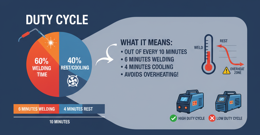
Arc welding machines of all types are rated according to their maximum current (amperage) output.
This rating is generally set by the manufacturers of the specific equipment in accordance with standards established by the NATIONAL ELECTRICAL MANUFACTURERS ASSOCIATION (NEMA).
These standards are established on a conservative basis, requiring a rating below the maximum overload capacity of the welding machine so that it will provide safe operation efficiently over a long period of time.
The duty cycle of a welding machine is the percentage of a (10) ten minute welding cycle that the welding machine can operate at its given maximum output current.
For example, if a welding machine is rated at 160 amp maximum at a 60% duty cycle, it means that the machine can be operated safely at maximum welding current (160 amp) for (6) six minutes out of every (10) ten minutes and would need to cool down, theoretically, for the remainder of (4) four minutes.
Welding machines are generally protected against overloading by thermal overload devices. This means that once the given duty cycle is exceeded, the excess heat being generated will activate the thermal overload device and shut of the power supply to the welding machine, preventing the overheating and failure of components.
Once the thermal overload is activated the machine should be left to cool down for the remainder of minutes out of (10) ten i.e. 60% actual welding time = (6) six minutes therefore the machine should be left to cool down for a further (4) four minutes.
Should the machine be located in a badly ventilated area or the ambient temperature where the machine is located is above 30°C, the fan cooling of components may not be sufficient and overheating of components can occur before the (6) six minute maximum welding cycle is reached.
Another influencing factor of overheating and cool down period, is whether the inside of the machine is cleaned out on a regular basis by using, for example, compressed air to remove dust and air-born metal particles that may have settled on the components of the machine.
If the welding amps required for a particular application is lower than the maximum output welding amps of the machine, the duty cycle is increased proportionately.
WELDING ELECTRODE STORAGE CONDITIONS
RE-DRYING PROCEDURES - HOT BOXES AND OVENS
GENERAL
To obtain a good quality weld using the MMAW (Manual Metal Arc Welding – stick) process depends on the composition and condition of the electrode coating. Because the flux coating and the alloy content in some of the flux coatings play such an important role in the welding process, no attempt should be made to weld with electrodes that have their coating wholly or partly damaged.
The efficiency of an electrode will also be impaired if the coating is allowed to get wet or damp. Dampness causes water vapour to be generated within the arc shield and adversely affects the weldability and quality of the weld deposit. This is especially important with all electrodes manufactured with coating of LOW HYDROGEN (Basic coated) specifications.
Hydrogen in the coating has an adverse effect on the welds requiring a tensile strength of 70,000 psi or more and causes internal and external porosity, underbead cracking and poor weldability.
STORAGE CONDITIONS
To prevent moisture pick-up, especially on LOW HYRDOGEN (Basic coated) electrodes, the electrodes should be stored in dry conditions, off the floor on pallets or racks, in their original packaging.
Hydrogen controlled basic coated electrodes are packed in cardboard cartons with a moisture resistant sealed polythene wrapping. Further protection is provided by packing these cartons into rigid outer shippers.
Once the polythene wrapping is removed the electrodes will, depending on the type of storage conditions, regain moisture from the surrounding air. It is therefore good practice to place the opened electrodes into a holding oven (HOTBOX) during welding and to re-seal unused electrodes in polythene sealed wrapping for storage and later use.
RE-DRYING AND RE-BAKING OF ELECTRODES
Electrodes that are suspected of possible dampness should be re-dried before use. The large range of electrodes that are manufactured with LOW HYROGEN controlled basic coatings need to be re-dried at varying temperatures. Electrodes that have been subjected to severe dampness or in contact with water need special re-baking procedures and it is recommended that your supplier be contacted for further information, inspection or advice.
SPECIAL NOTE
Repeated re-baking has an adverse effect on the electrode coating strength and adhesion to the electrode core wire. It is therefore recommended that re-baking of electrode be limited to 2 times.
RECOMMENDED RE-BAKING PROCEDURES FOR ELECTRODES
| Type of Electrode | Time in Hours | Temperatures °C (Min-Max) |
|---|---|---|
| RUTILE COATED (E 6013) | 1-2 | 100-120 |
| CELLULOSIC (E6010) & GOUGE | NOT RECOMMENDED | ------------ |
| LOW HYDROGEN (BASIC COATED) | 1-2 | 350-370 |
| LOW ALLOY (CHROME/MOLY RANGE) | 1-2 | 400-420 |
| 300 SERIES STAINLESS STEEL | 1-2 | 350-370 |
| CAST IRON | 2-3 | 120-150 |
| HARDFACING | 1-3 | 350-370 |
GAS WELDING & CUTTING SAFETY PRACTICES
Applying and observing basic safety measures during GAS WELDING AND CUTTING operations is a pre-requisite in preventing - serious injury or even death of the operator - damage to expensive equipment - facilities - costly downtime.
Listed below is a number of important steps that should be taken when fitting and before the actual use of the gas equipment. These steps, if strictly applied, will ensure that the correct flow, regulation and mixing of the gases is obtained and that the ignition of the flame is done safely.
- No gas equipment repairs should be attempted on site and worn or leaking components should be replaced immediately.
- The pressure regulators are precision instruments and should not be exposed to shocks, vibration or impact caused by the sudden opening of the cylinder valves while the regulator diaphragm is under pressure.
- Gas bottles with regulators fitted to them and with safety caps in place should always be secured with chains or fitted securely onto cylinder trolleys. Always store and use the cylinders in the upright position.
- Never lubricate components using oil, grease or hydrocarbon or let similar organic materials come in contact with the gas equipment. It can cause a violent explosion. Do not use oil based P.T.F.E. tape to stop leaks, rather replace the component.
- When testing for leaks or cleaning the equipment, use a soapy water solution.
- Do not use regulators on any gas other than the one that it is designed for.
- Never operate the equipment at pressures exceeding those that are recommended by the manufacturer.
- Where practical avoid using long lengths of hose as they are vulnerable to mistreatment i.e. stepped on, run over, kinked, tangled, sparks, hot slag, hot/sharp edges, open flames, exposed to sun for long periods etc. Keep hose away from oil and grease. Purge gas from pipes after use. Never use steel or copper pipe to make a joint. Do not repair hose with tape. Regular inspection of hose quality and soundness of connections will prevent costly down time.
- The gas cylinders and the bullnose on the regulators have their own seat and may not seat properly the first time. To ensure that proper seating is achieved when fitting the regulator, the following procedure is recommended:
- Fit the regulator bullnose to the cylinder valve and tighten the regulator nut slightly. Turn the regulator clock and anti-clock wise a number of times.
- Remove the regulator and inspect the seating marks achieved on the bullnose. This should indicate if proper seating is being achieved, thereby avoiding leaks. Some cylinder valve seats may be damaged.
- Damaged bullnose stem faces and regulator nuts should be replaced as this is the main cause of leakages.
- Before refitting the regulator, open and shut the cylinder valve to remove any dirt or foreign particles that may have lodged in the valve.
- Once proper seating is achieved, re-fit the regulator and tighten the nut securely.
- The same procedure is recommended to attain proper seating of the cutting nozzles to the torch head. This procedure will also ensure proper gas flow, no leakage and reduce the possibility of flash backs.
- Ensure that the gas hoses from the regulator to the torch are in good condition and that all connections are secured, to avoid possible leakages.
- It is highly recommended, to ensure operator safety, to fit flash back arrestors to the regulator and torch flow system.
- Before opening the cylinder valves, release the pressure valve on the regulator by turning the pressure knob anti-clock wise. This will ensure that the sudden high pressure loading from the cylinder does not damage the regulator diaphragm or gauges. On opening the cylinder valve the high pressure gauge will indicate the content capacity of the cylinder. The low pressure gauge should be on zero.
- Stand to the side of the regulators when opening the cylinders. Avoid being behind or in front of the regulator gauges. This is for your own safety.
- Open the cylinder valves slowly.
- Set the regulator low pressure required for the size of nozzle and job at hand.
- When lighting the torch, open the acetylene torch valve first and when the job is finished close the acetylene torch valve first.
- After the job is completed, close the cylinder valves first, purge the gas from the hoses by opening the torch valves and finally release the pressure valve of the regulator's diaphragm. This will ensure that the next time the system is used the correct safety procedures are re-applied.
- Finally, ensure that the operator has adequate eye protection fitted with the correct shade lenses, adequate ventilation and/or correct respiratory protection, safety gloves, safety shoes, shoe spats, leather apron and flame retardant overalls, without pockets and/or turn-up hems or sleeves where sparks or hot metal can collect and cause burns or fires.
- Do not weld, cut or heat near flammable material and at all times be safety conscious.
STAINLESS STEEL WELD CLEANER
DESCRIPTION
Stainless Steel Weld Cleaner is a thickened solution of special acids used for the removal of the black oxide marks or burn scale left during the welding of stainless steel.
After the use of Stainless Steel Weld Cleaner the weld area treated should have the same appearance as the rest of the stainless steel being used. The stainless steel weld area will have a clean professional surface finish.
PHYSICAL PROPERTIES
- Boiling point: N/A
- Specific Gravity: 1.24-1.26
- Water Solubility: MISCIBLE
- pH (as supplied): < 1.0
- Appearance/colour: OPAQUE, YELLOW ACIDIC, PUNGENT ACIDIC ODOUR
METHOD OF APPLICATION
- Clean the weld area carefully using a stainless steel brush.
- Stir the content of the container with a flat plastic or wooden stick to ensure a smooth consistency, especially if the product has not been used for a long time.
- Ensure that the surface is cool before applying paste.
- Apply weld cleaner to the area to be cleaned, using a non-metallic applicator.
- Leave paste on the surface for 1 to 5 minutes, depending on the severity of the oxide scale or burn marks. Care should be taken to avoid getting excess paste onto bright or polished surfaces, as this may cause stains or unsightly dull patches.
- Remove residue by rinsing with water. It may be necessary to scrub the area with a stainless steel wire brush to remove any visible etching to match the remaining surface.
SAFETY PRECAUTIONS
- The Stainless Steel Weld Cleaner contains a mixture of NITRIC ACID, HYDROFLUORIC ACID, HYDROCHLORIC ACID and is EXTREMELY CORROSIVE.
- Avoid contact with the skin and eyes by wearing protective clothing, eye protection and breathing apparatus at all times when working with this product.
- Do not use near open flames or cutting torches, since hazardous flammable gas can be generated.
- Keep out of reach of children and give all personnel suitable instructions regarding the dangers before allowing them to work with the product.
- In case of accidental contact with the skin or eyes, wash immediately with water for 15 minutes and seek medical attention. Physicians should treat for Hydrofluoric acid burns.
- In case of accidental spillage - SMALL SPILL: Take up with sand or other non-combustible absorbent material and place in container for later disposal – LARGE SPILL: Ensure that clean-up is conducted by trained personnel. Contain spill with earth, sand or absorbent material that does not react with the product. Do not use organic material such as sawdust.
- Do not store or use below 5° C.
WELDING SAFETY INFORMATION
PRIMARY INPUT VOLTAGE
The primary voltage shock is very hazardous because it is much greater than the welding machine secondary voltage. You can receive a shock from the primary (input) voltage if you touch a lead inside the welding machine with the power to the welder "on" while you have your body or hand on the welding machine case or other grounded metal.
Remember that turning the welding machine power switch "off" does not turn the power off inside the welding machine. The input power cord must be unplugged or the power disconnect switch turned off. This also applies when you remove the welding machine panels.
Should a problem occur with the welding machine it is always advisable to have a qualified electrician repair the unit. It is also good practice to have your welding machine installed by a qualified electrician so that it is correctly wired for the primary voltage supply recommended by the manufacturer and that the case be connected to an earth ground.
The case must be grounded so that if a problem develops inside the welding machine, a fuse will blow, letting you know that the welding machine needs attention. Never ignore a blown fuse as it is a warning that something is wrong.
SECONDARY OUTPUT VOLTAGE
A secondary voltage shock occurs when you touch a part of the electrode circuit while at the same time another part of your body is touching the metal upon which you are welding. To receive a shock your body must touch both sides of the welding circuit i.e. electrode and ground (workpiece) at the same time.
To prevent secondary voltage shock you must develop and use safe work habits:
- Wear dry gloves and clothes, in good condition, when welding
- Do not touch the electrode or metal parts of the electrode holder with your skin or wet clothing
- Ensure that the electrode holder jaws, handle and cable insulation is in good condition
- Never weld on wet or metal floors without proper dry insulation i.e. wood or rubber mats, between your body (including arms and legs) and the metal workpiece being welded
- Do not rest your body, arms or legs on the workpiece, especially if your clothing–gloves are wet or bare skin is exposed
Remember that the (stick) electrode is always "electrically hot" when the welding machine is switched on and should be treated with respect.
These rules are basic to all welding processes and you will probably not experience a shock if you adhere to them.
TROUBLESHOOTING GUIDE ON WELDING EQUIPMENT
| Problem | Cause | Remedy |
|---|---|---|
| Welder will not start | Power switch not turn on | Place power switch to "ON" position |
| Supply line fuse blown | Replace fuse (Check cause first) | |
| Power circuit dead | Check input voltage | |
| Overload relay tripped | Cool down unit (remove cause) | |
| Loose or broken power, electrode or ground lead | Replace, tighten or repair | |
| Wrong voltage | Check input voltage per manual | |
| Polarity switch not centered (AC-DC) | Centre switch on +, -, or AC or DC | |
| Open circuit to switch | Repair | |
| Welder starts but blows fuse after welding begins | Short circuit in electrical components of welder | Check connections and lead insulation |
| Fuse to small | Check manual for correct fuse size | |
| Welder welds but soon stops welding | Proper air ventilation obstructed | Make sure that all case ventilation openings free and clean |
| Cooling fan not working | Replace or repair leads and connections | |
| Overloading – welding in excess of rating | Operate at rated load & duty cycle | |
| Variable & sluggish arc | Current to low | Check recommended current for electrode type and size |
| Low line voltage | Check input line voltage | |
| Welding cables to small | Check recommended cable sizes | |
| Poor earth, electrode or control circuit connection | Check all connections. Clean or replace | |
| Welding arc is load and spatters excessively | Current setting is to high | Check recommended setting according to electrode type or size |
| Polarity setting is wrong | Check recommended polarity. Try reversing polarity or change electrode | |
| Polarity switch wont work | Contacts worn, rough and pitted from improper switch while welder is under load | Replace switch. Never operate switch while welder is under load |
| Welder will not switch off | Line switch has failed mechanically | Replace switch |
| Arcing at earth clamp | Loose connection or weak clamp spring | Tighten connection or replace earth clamp. Positive and firm earth = good welds |
| Electrode holder becomes hot | Loose connection, loose jaw, loose electrode clamping, inadequate duty cycle of holder | Tighten cable connection to holder or replace holder with correct duty cycle size |
| Electrical shock when touching welder | Frame not grounded | See welder instruction manual for proper grounding procedure of welder covers |
| Welding cables hot | Incorrect duty cycle of cable | Check recommended cable size according to welders manual |
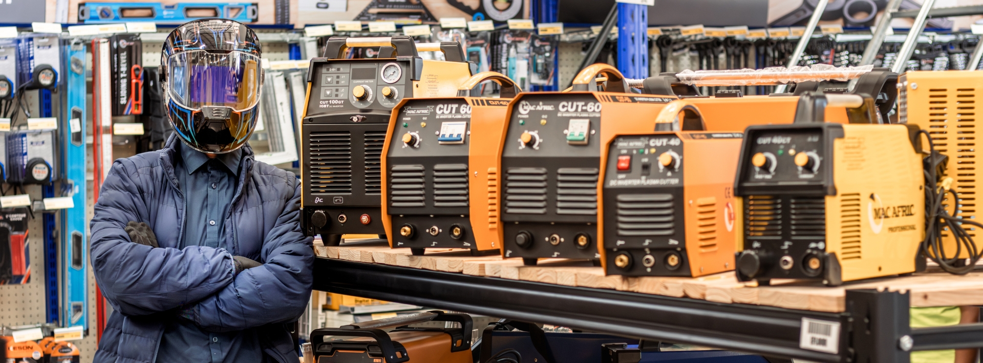
PLASMA ARC CUTTING
The Plasma Arc Cutting system employs the use of an electric arc and a pressurised volume of ionised air forced through a small orifice (TIP) fitted between the electrode in the plasma torch and the workpiece to be cut. This constricted, high speed and high temperature plasma arc stream cuts through metal in a concentrated localised area and the molten metal is blown away by the high velocity arc and air steam.
The Plasma Arc Cutting process is capable of cutting and gouging most Ferrous (steel) and Non-Ferrous (Aluminium, Copper etc) metals producing a clean narrow cut width (determined by the tip orifice size) and smoother surfaces.
The process is more portable, cuts faster and cleaner than the gas cutting (oxy/fuel) process, requiring no pre-heat, and with the added advantage of being able to cut Stainless Steel and Non-Ferrous metals (oxy/fuel cannot) cleanly and effectively, using less cumbersome equipment. The process can be used with either a hand held torch or on automated systems.
The Plasma Power source has drooping current characteristics, using higher voltages than standard welding machines and the torches are well insulated to protect the operator against the high voltages present.
The majority of Plasma Arc Cutters today have high frequency arc starting features meaning that non base metal contact is used as opposed to machines without high frequency that require scratch start to initiate the arc.
Hand cutting torches using stand-off guides (determines tip distance from workpiece) enables the operator to rest the torch on the workpiece and by using a template or straight edge is able to cut straight or profile edges cleanly and accurately. The torch can also be used for gouging by changing the tip to a gouging tip that enables the operator to angle the torch to ± 30 degrees as opposed to the 90 degree used when cutting.
Long (extended) tips can be fitted for maximum visibility giving a clear view of the cut to be made either in the stand-off or drag position. The tips contain an orifice which constricts the plasma arc. The tips come in various orifice sizes and also gradually wear with use and must be replaced when the arc cut becomes too wide.
Due to the alloying denseness and higher electrical resistance of Stainless Steel the thickness of cut achieved per cutting machine capacity is considerably lower than steel. All manufactures of Plasma Arc Cutting equipment indicate the cutting capacity when cutting various metals.
When cutting a circle the cut is started at the plate leading edge towards the circle edge or a hole is pierced in the centre of the circle and cut towards the circle edge. On piecing the hole through the plate the torch is angled at ± 30º and once pieced the torch is raised to a 90º position.
PROBLEM SHOOTING AND MAINTENANCE
- The operating voltages for Plasma Arc Cutting can reach 400 volt D.C. and most systems incorporate safety features that prevent the operator from coming into contact with the high voltage. Before using the system the operator must ensure that the torch cable is not damaged or punctured and that the electrode, tip and shield cup is fitted correctly, securely and in good condition. All access panels must be closed at all times when the power is connected.
- It is recommended that periodic cleaning using dry compressed air, of the interior of the power source is done to ensure that metal containing dust does not damage the electronic components. When this is done the power to cutter must be disconnected first for you own safety.
- Fumes and gases produced by the Plasma Arc Cutting can be hazardous to health and must be avoided. Use the necessary respiratory protection masks or respirators when cutting in unventilated or confined areas.
- Sparks from the Plasma Arc Cutting can be a fire hazard and all combustible material and solvents should be kept away from the cutting area.
- The Plasma Arc emits intense, visible, infrared and ultraviolet radiation which can be harmful to the eyes and skin. The same eye and skin protection normally used for GTA (T.I.G.) welding at the equivalent current range should be used.
- Water vapour and oil introduced into the highly concentrated constricted arc can damaged the electrode, tip and shield cup and depending on the severity of the water or oil "explosion" within the arc, damage to the entire torch head is possible. It is recommended that the water/oil trap fitted to the air supply system of the cutting machine is cleaned at regular intervals. Should water/oil still persist, it is recommended that a second water/oil trap be installed at the compressor outlet.