MAC AFRIC Drill Bit Sharpeners: Operation Manual Guide
MAC AFRIC Drill Bit Sharpeners: Operation Manual Guide
Looking to extend the life of your drill bits and save on replacement costs? The MAC AFRIC Drill Bit Sharpener range offers quick, accurate, and user-friendly sharpening solutions for workshops of all sizes. This guide presents the complete operation manuals for two models in the range the TDRILS213 120W and the TDRILS226 450W covering everything from specifications and setup to maintenance and parts identification.
Both sharpeners feature durable diamond grinding wheels for consistent results, adjustable point angle settings, and reliable DC motors. Whether you're sharpening smaller HSS bits or tackling larger drill diameters, there's a model suited to your needs.
What You'll Learn in This Manual
Model Overview
The MAC AFRIC Drill Bit Sharpener range currently includes two models. The TDRILS213 is a compact 120W unit suited to smaller drill bits from Ø3–Ø13mm, while the TDRILS226 is a heavier-duty 450W model designed for larger bits from Ø12.1–Ø26mm. Both share the same operating principle and point angle range of 95°–135°, and both include a CBN grinding wheel suitable for HSS drill bits.
Specifications
TDRILS213 – Drill Bit Sharpener 120W
| Specification | Value |
|---|---|
| Model | TDRILS213 |
| Motor Power / Speed | 230V, 50/60Hz, 120W / 4400rpm |
| Grinding Range | Ø3–Ø13mm (up to Ø15mm) |
| Point Angle | 95°–135° |
| Weight | 9 kg |
| Dimensions | 32 × 18 × 19 cm |
TDRILS226 – Drill Bit Sharpener 450W
| Specification | Value |
|---|---|
| Model | TDRILS226 |
| Motor Power / Speed | 220–240V, 50/60Hz, 450W / 4400rpm |
| Grinding Range | Ø12.1(8)–Ø26mm (up to Ø32mm) |
| Point Angle | 95°–135° |
| Weight | 30 kg |
| Dimensions | 46 × 24 × 22 cm |
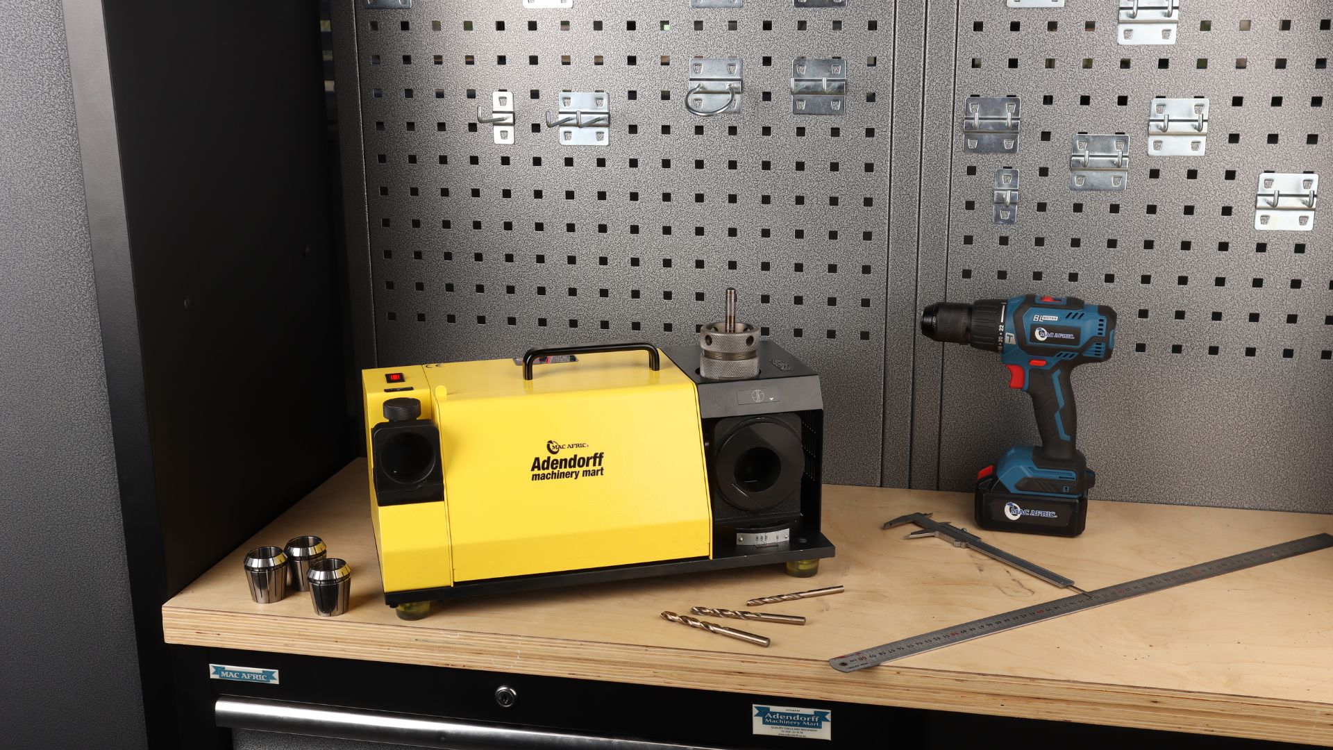
Standard Equipment
TDRILS213 – 120W
- Grinding wheel: CBN (for HSS) × 1 piece
- 11 collets: Ø3–Ø13 collet chuck × 1 piece
- Electric cable × 1 piece
- Hexagon wrench (M5) × 1 piece
TDRILS226 – 450W
- Grinding wheel: CBN (for HSS) × 1 piece
- 14 collets: Ø13–Ø26 collet chuck × 1 piece
- Electric cable × 1 piece
- 7 pcs hexagon wrench (2, 2.5, 3, 4, 5, 6, 8mm)
- Wrench (17–19mm) × 1
Safety Warnings
Important: Read all instructions before use.
Do not operate in damp, wet, or explosive environments. Avoid flammable liquids and gases. Keep children and bystanders away from the work area.
Work Area Safety
Keep work area clean and well lit. Cluttered or dark areas increase risk of accidents.
Electrical Safety
- Prevent electric shock by avoiding contact with earthed surfaces such as pipes or radiators.
- Always disconnect the tool when not in use, before servicing, or when changing accessories.
- Do not use damaged cables or plugs. Replace immediately.
Personal Safety
- Stay alert. Do not use when tired or under the influence of alcohol, drugs, or medication.
- Wear appropriate PPE: safety glasses, hearing protection, and close-fitting clothing.
- Tie back long hair and remove jewellery that may get caught in moving parts.
- Maintain proper footing and balance at all times.
Tool Use Safety
- Use only accessories recommended by Adendorff.
- Do not force the tool. Use the correct tool for the application.
- Inspect for damaged parts before use. Do not operate with broken or misaligned components.
- Do not operate if the switch does not function properly.
Operation
The following operating procedures apply to both the TDRILS213 and the TDRILS226. Where drill size ranges differ between models, the relevant range is noted.
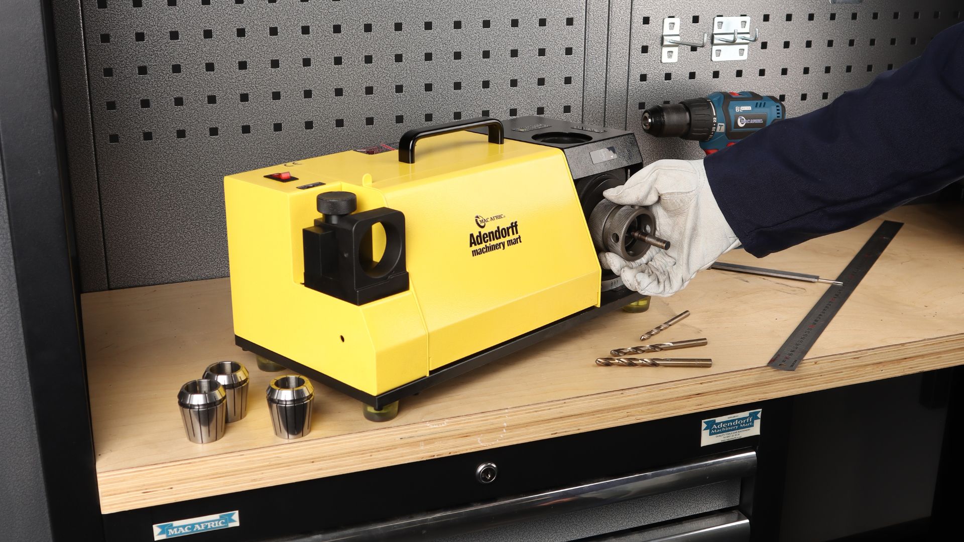
A. Setting Up the Drill Bit in the ER Collet Chuck
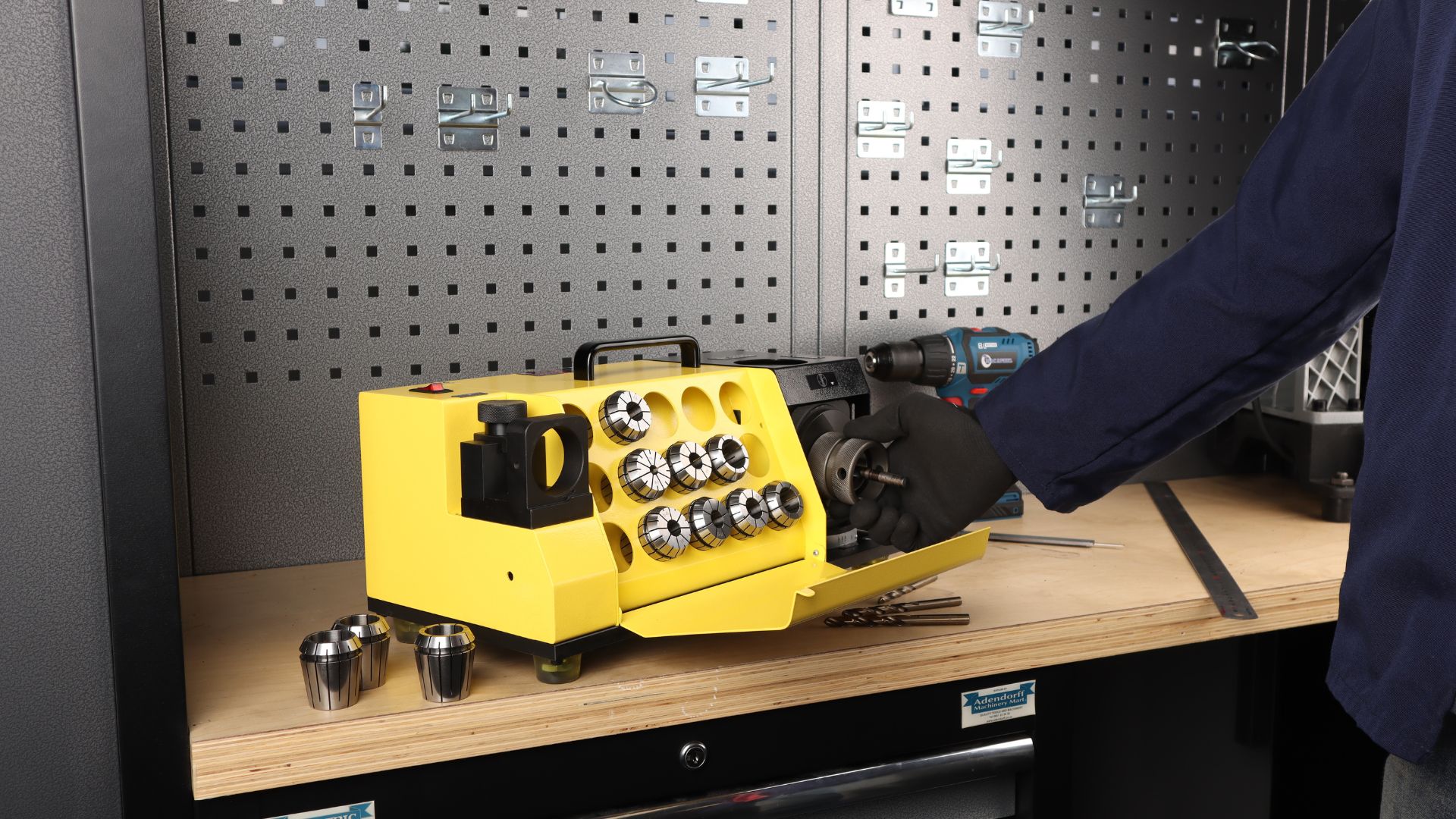
- Determine the diameter of your drill bit and select the appropriate collet and chuck.
- Insert the collet into the chuck at a 45° angle and tighten the nut slightly.
- Insert the drill bit so that approximately 35 mm extends beyond the chuck. Do not fully tighten yet.
Note
The clamping nut must not be fully fastened at this stage. The drill bit must remain adjustable.
B. Aligning the Drill Bit
- Reset the scale ring by turning it fully clockwise, then anti-clockwise to match the drill size.
- Insert the chuck set into the web adjustment shelf and tighten clockwise.
- Push the drill fully in and turn it clockwise.
- Tighten the chuck set securely, then gently remove.
Note
Ensure the drill cutting lip is parallel with the clamping nut slot before grinding. Adjust if necessary.
C. Grinding the Point Angle
- Switch on the power and allow 10 seconds for the motor to stabilise.
- Insert the chuck set into the point angle grinding shelf, aligning pins correctly.
- Move the drill gently left and right until the grinding sound stops.
- Rotate and repeat for the opposite side.
TDRILS213 Drill Size Range
Ø3–Ø13 mm (up to Ø15 mm)
TDRILS226 Drill Size Range
Ø12.1–Ø26 mm (up to Ø32 mm)
Point Angle Range (Both Models)
95°–135°
D. Grinding the Lip Relief Angle
- Insert the chuck set into the lip relief angle grinding shelf.
- Move left and right until grinding sound stops, then repeat on the other side.
Attention
If the cutting lip points downward, increase the web adjustment scale. If upward, decrease it. Shorter drill flute lengths increase web thickness adjust the web scale accordingly.
Maintenance
1. Cleaning & Rust Prevention
- Remove debris after use.
- Apply a rust inhibitor to metal parts before storage.
2. Lubrication & Inspection
- Lubricate bearings and moving parts regularly with heat-resistant grease.
- Inspect the grinding wheel for cracks or heavy wear. Replace immediately if damaged.
- Ensure all fasteners are secure.
3. Storage & Safety
- Store in a dry place, covered when not in use.
- Regularly inspect power cables, switches, and fuses.
Replacing the Wheel
A. Open the Wheel Cover
- Ensure the power cord is unplugged before proceeding.
- Use a 4 mm hex wrench to loosen the screw and open the cover.
B. Removing and Replacing the Grinding Wheel
- Use a brush to clean the machine, then wipe the surface with a dry cloth.
- If the machine was recently used, wait at least 3 minutes for the grinding wheel to cool down.
- Hold the wheel firmly with your left hand. Using your right hand, turn the screw counterclockwise with a 4mm hex wrench to loosen it.
- Remove the diamond grinding wheel from the machine.
- Insert the new grinding wheel.
- Place the wheel onto the motor's principal axis, then tighten the screw and reinstall the wheel cover to complete the replacement.
Warning: Always disconnect power before replacing the wheel.
The motor shaft is a precision component. Incorrect installation may damage the wheel or affect alignment.
Troubleshooting
The following troubleshooting guide applies to both models.
| No. | Issue | Possible Cause | Solution |
|---|---|---|---|
| 1 | Machine won't turn on | Voltage instability or blown fuse | Check/replace the fuse |
| 2 | Motor not running (switch is on) | Loose or detached wiring | Inspect and reconnect wires |
| 3 | Burning smell from motor | Motor failure | Replace the motor immediately |
| 4 | Drill bit not grinding properly | Incorrect grinding wheel for bit material | Use the correct wheel (CBN for HSS, SD for carbide) |
| 5 | Drill bit still not grinding | Grinding wheel worn or damaged | Replace the grinding wheel |
Parts List
TDRILS213 – Parts List
Parts diagram components: 1. Motor switch, 2. Collet chuck, 3. Handle, 4. Center adjustment, 5. Pin, 6. Lip relief angle shelf, 7. Fan blade, 8. Point angle shelf, 9. Point angle adjustment, 10. Alignment base, 11. Adjustment scale, 12. Collet.
| No. | Part Name | Qty. | No. | Part Name | Qty. |
|---|---|---|---|---|---|
| 1 | Backplane | 1 | 20 | M6x16 Screw | 1 |
| 2 | M6x20 Screw | 2 | 21 | Motor plate | 1 |
| 3 | Spring Washer 6 | 2 | 22 | Spring 1x11x45 | 1 |
| 4 | Flat washer 6.7x13x1.9 | 2 | 23 | Single Hole Plate | 1 |
| 5 | M5x10 Cross-head Screw | 6 | 24 | Elastic Pin 3x10 | 2 |
| 6 | Rubber Foot Pad M5 | 4 | 25 | Long Threaded Rod | 1 |
| 7 | Grinding Seat | 1 | 26 | M8x12 Screw | 1 |
| 8 | Grinding Seat Screw | 1 | 27 | Dust Washer | 1 |
| 9 | M5x16 Screw | 2 | 28 | Motor | 1 |
| 10 | Grinding Wheel Cover | 1 | 29 | Shell Assembly | 1 |
| 11 | M5x10 Screw | 1 | 30 | M4x8 Screw | 4 |
| 12 | Grinding Wheel Gasket | 1 | 31 | Flat washer 4 | 4 |
| 13 | Heat Dissipation Blade | 1 | 32 | Switch Assembly | 1 |
| 14 | Grinding Wheel | 1 | 33 | M4x12 Screw | 5 |
| 15 | Aluminum Core | 1 | 34 | Lock Washer 4 | 1 |
| 16 | M6x8 Screw | 3 | 35 | Aluminum Grounding Sign φ5 | 1 |
| 17 | M5x25 Screw | 2 | 36 | Collet Chuck | 1 |
| 18 | Spring Washer 5 | 2 | 37 | Alignment Base | 1 |
| 19 | Flat washer 5.6x11x1.4 | 2 |
TDRILS226 – Parts List
Parts diagram components: 1. Motor switch, 2. Handle, 3. Collet chuck, 4. Point angle shelf, 5. Point angle adjustment, 6. Collet, 7. Alignment base, 8. Adjustment scale.
| No. | Part Name | Qty. | No. | Part Name | Qty. |
|---|---|---|---|---|---|
| 1 | Backplane | 1 | 20 | M8x60 Screw | 1 |
| 2 | Big Washer 12 | 3 | 21 | M6x16 Screw | 1 |
| 3 | Spring Washer 12 | 3 | 22 | Single Hole Plate | 1 |
| 4 | M12x30 Bolt | 3 | 23 | Elastic Pin 4x12 | 1 |
| 5 | Rubber Foot Pad | 4 | 24 | M6x25 Screw | 1 |
| 6 | Grinding Seat | 1 | 25 | M8 Nut | 2 |
| 7 | M5x16 Screw | 12 | 26 | M4x8 Screw | 1 |
| 8 | Grinding Block Screw | 1 | 27 | Motor plate | 1 |
| 9 | Flat Washer 5 | 6 | 28 | Motor | 1 |
| 10 | M5x10 Screw | 4 | 29 | Spring Washer 5 | 4 |
| 11 | M5 Nut | 2 | 30 | M5x25 Screw | 4 |
| 12 | Kaiping Hinge | 1 | 31 | Shell Assembly | 1 |
| 13 | Grinding Wheel Cover | 1 | 32 | Switch | 1 |
| 14 | M5x10 Screw | 1 | 33 | M4x12 Screw | 1 |
| 15 | Grinding Wheel Gasket | 1 | 34 | Lock Washer 4 | 1 |
| 16 | Heat Dissipation Blade | 1 | 35 | Aluminum Grounding Sign φ5 | 1 |
| 17 | Grinding Wheel | 1 | 36 | Collet Chuck | 1 |
| 18 | M6x8 Screw | 3 | 37 | Alignment Base | 1 |
| 19 | Aluminum Core | 1 |
Note
Refer to the diagram provided. Ensure all replacement parts are sourced from authorised Adendorff outlets.
Warranty
WARRANTY TERMS AND CONDITIONS
Warranty Period
12 months from purchase date (first user only).
Coverage
Manufacturing and material defects. Excludes: batteries, chargers, wear parts (bearings, brushes, cables, plugs), accessories (drills, drill bits, saw blades).
Exclusions
Misuse, maltreatment, accidents, or modifications. Overloading, fluid ingress, excessive dust, or intentional damage. Failure to follow instructions or use correct voltage.
Liability
Adendorff Machinery Mart accepts no liability for injuries caused by improper use.
Repairs
Warranty repairs must be carried out at authorised Adendorff repair centres. A 3-month warranty applies to all repairs.
Transport Costs
Transport is the customer's responsibility unless agreed in writing.
Claims
Warranty claims require proof of purchase. Claims do not extend or reset the warranty period.
Returns
Return product intact, clean, and in original case (if applicable). Include proof of purchase.
For full warranty details, visit www.adendorff.co.za or call 011 434 7000.
Final Note
This manual provides the complete operational guidance for the TDRILS213 120W and TDRILS226 450W Drill Bit Sharpeners. Following these procedures will ensure safe operation, consistent sharpening results, and long service life from your machine. Keep this manual accessible for all operators and refer to it regularly.
DANGER! Read all safety regulations and instructions.
Keep all safety regulations and instructions in a safe place for future use.
Supplied by:
Adendorff Machinery Mart
98 Sailor Malan Avenue, Aeroton, Johannesburg, 2190
www.adendorff.co.za