How to Use a Milling Machine
Listen to a podcast about this article
Instructions: How to Use a Milling Machine
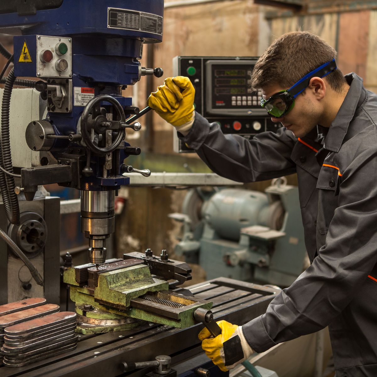
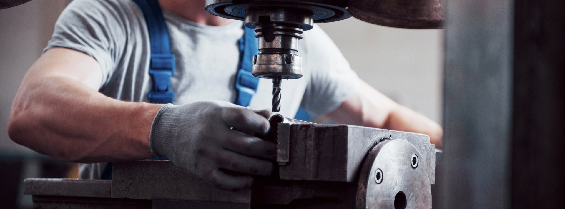
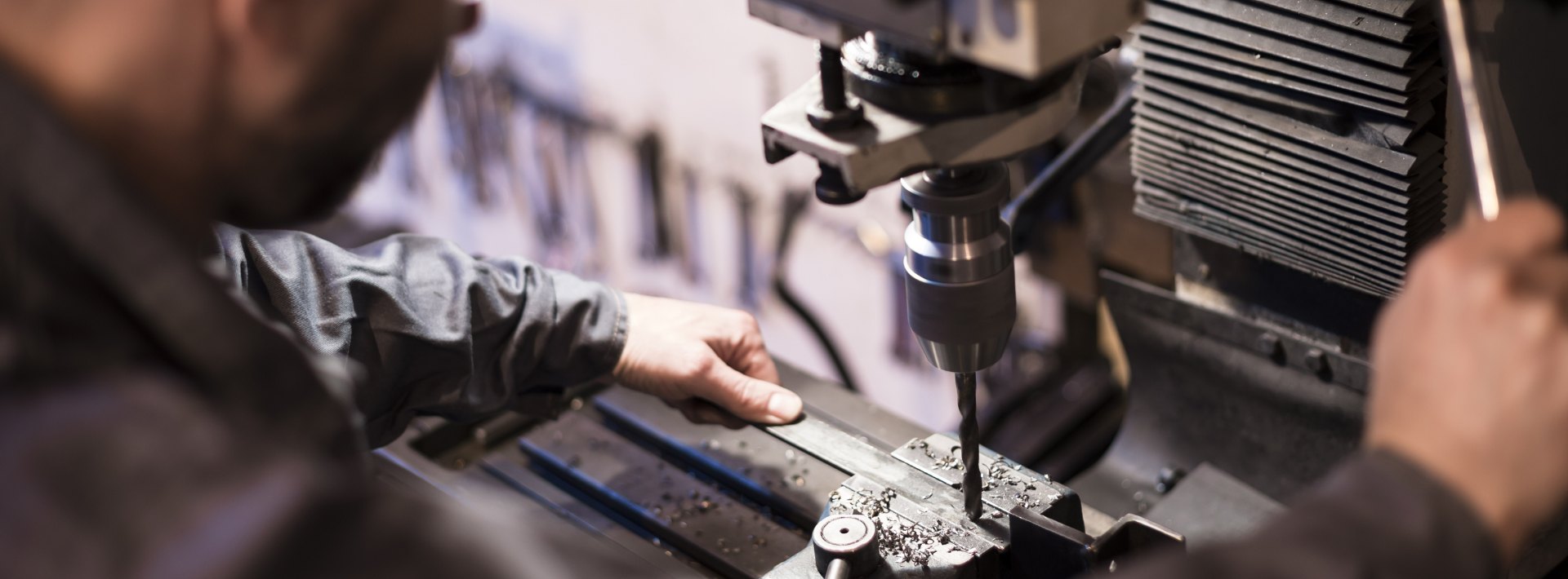
Milling is the process of machining flat, curved, or irregular surfaces by feeding the workpiece against a rotating cutter containing a number of cutting edges. The usual mill consists basically of a motor-driven spindle, which mounts and revolves the milling cutter, and a reciprocating adjustable worktable, which mounts and feeds the workpiece.
Milling machines are basically classified as vertical or horizontal. These machines are also classified as knee-type, ram-type, manufacturing or bed type, and planer-type. Most milling machines have self-contained electric drive motors, coolant systems, variable spindle speeds, and power-operated table feeds.
At Adendorff Machinery Mart, you'll find a comprehensive range of milling machines suitable for all skill levels and applications.
Milling Machines


Types of Milling Machines
Knee-Type Milling Machines
Knee-type mills are characterised by a vertically adjustable worktable resting on a saddle which is supported by a knee. The knee is a massive casting that rides vertically on the milling machine column and can be clamped rigidly to the column in a position where the milling head and milling machine spindle are properly adjusted vertically for operation.
Plain Vertical Machines
Plain vertical machines are characterised by a spindle located vertically, parallel to the column face, and mounted in a sliding head that can be fed up and down by hand or power. Modern vertical milling machines are designed so the entire head can also swivel to permit working on angular surfaces.
The turret and swivel head assembly is designed for making precision cuts and can be swung 360° on its base. Angular cuts to the horizontal plane may be made with precision by setting the head at any required angle within a 180° arc.
Plain Horizontal Milling Machines
The plain horizontal milling machine's column contains the drive motor and gearing and a fixed position horizontal milling machine spindle. An adjustable overhead arm containing one or more arbor supports projects forward from the top of the column. The arm and arbor supports are used to stabilise long arbors. Supports can be moved along the overhead arm to support the arbor where support is desired depending on the position of the milling cutter or cutters.
The milling machine's knee rides up or down the column on a rigid track. A heavy, vertical positioning screw beneath the knee is used for raising and lowering. The saddle rests upon the knee and supports the worktable. The saddle moves in and out on a dovetail to control cross feed of the worktable. The worktable traverses to the right or left upon the saddle for feeding the workpiece past the milling cutter. The table may be manually controlled or power fed.
Universal Horizontal Milling Machine
The basic difference between a universal horizontal milling machine and a plain horizontal milling machine is the addition of a table swivel housing between the table and the saddle of the universal machine. This permits the table to swing up to 45° in either direction for angular and helical milling operations. The universal machine can be fitted with various attachments such as the indexing fixture, rotary table, slotting and rack cutting attachments, and various special fixtures.
Ram-Type Milling Machine
The ram-type milling machine is characterised by a spindle mounted to a movable housing on the column to permit positioning the milling cutter forward or rearward in a horizontal plane.
Universal Ram-Type Milling Machine
The universal ram-type milling machine is similar to the universal horizontal milling machine, the difference being, as its name implies, the spindle is mounted on a ram or movable housing.
Swivel Cutter Head Ram-Type Milling Machine
The cutter head containing the milling machine spindle is attached to the ram. The cutter head can be swivelled from a vertical spindle position to a horizontal spindle position or can be fixed at any desired angular position between vertical and horizontal. The saddle and knee are hand driven for vertical and cross feed adjustment whilst the worktable can be either hand or power driven at the operator's choice.
Safety Rules for Milling Machines
Milling machines require special safety precautions whilst being used. These are in addition to those safety precautions described in Chapter 1.
- Do not make contact with the revolving cutter.
- Place a wooden pad or suitable cover over the table surface to protect it from possible damage.
- Use the buddy system when moving heavy attachments.
- Do not attempt to tighten arbor nuts using machine power.
- When installing or removing milling cutters, always hold them with a rag to prevent cutting your hands.
- Whilst setting up work, install the cutter last to avoid being cut.
- Never adjust the workpiece or work mounting devices when the machine is operating.
- Chips should be removed from the workpiece with an appropriate rake and a brush.
- Shut the machine off before making any adjustments or measurements.
- When using cutting oil, prevent splashing by using appropriate splash guards. Cutting oil on the floor can cause a slippery condition that could result in operator injury.
NOTE: Chip rake should be fabricated to the size of the T-slots.
Tools and Equipment: Milling Cutters
Classification of Milling Cutters
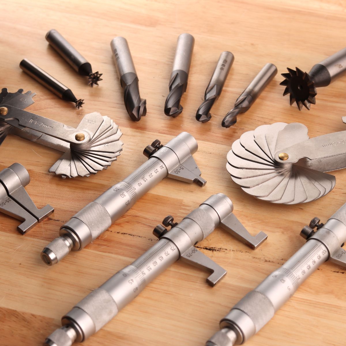
Milling cutters are usually made of high-speed steel and are available in a great variety of shapes and sizes for various purposes. You should know the names of the most common classifications of cutters, their uses, and, in a general way, the sizes best suited to the work at hand.
Milling Cutter Nomenclature
The following parts and angles in some form are common to all cutter types:
- The pitch refers to the angular distance between like or adjacent teeth. The pitch is determined by the number of teeth.
- The tooth face is the forward facing surface of the tooth that forms the cutting edge.
- The cutting edge is the angle on each tooth that performs the cutting.
- The land is the narrow surface behind the cutting edge on each tooth.
- The rake angle is the angle formed between the face of the tooth and the centreline of the cutter. The rake angle defines the cutting edge and provides a path for chips that are cut from the workpiece.
- The primary clearance angle is the angle of the land of each tooth measured from a line tangent to the centreline of the cutter at the cutting edge. This angle prevents each tooth from rubbing against the workpiece after it makes its cut.
- The hole diameter determines the size of the arbor necessary to mount the milling cutter.
Plain milling cutters that are more than 3/4 inch in width are usually made with spiral or helical teeth. A plain spiral-tooth milling cutter produces a better and smoother finish and requires less power to operate. A plain helical-tooth milling cutter is especially desirable when milling an uneven surface or one with holes in it.
Types of Teeth
The teeth of milling cutters may be made for right-hand or left-hand rotation, and with either right-hand or left-hand helix. Determine the hand of the cutter by looking at the face of the cutter when mounted on the spindle. A right-hand cutter must rotate counter-clockwise; a left-hand cutter must rotate clockwise. The right-hand helix is shown by the flutes leading to the right; a left-hand helix is shown by the flutes leading to the left. The direction of the helix does not affect the cutting ability of the cutter, but take care to see that the direction of rotation is correct for the hand of the cutter.
Saw Teeth
Saw teeth are either straight or helical in the smaller sizes of plain milling cutters, metal slitting saw milling cutters, and end milling cutters. The cutting edge is usually given about 5 degrees primary clearance. Sometimes the teeth are provided with off-set nicks which break up chips and make coarser feeds possible.
Helical Milling Cutters
The helical milling cutter is similar to the plain milling cutter, but the teeth have a helix angle of 45° to 60°. The steep helix produces a shearing action that results in smooth, vibration-free cuts. They are available for arbor mounting, or with an integral shank with or without a pilot. This type of helical cutter is particularly useful for milling elongated slots and for light cuts on soft metal.
Metal Slitting Saw Milling Cutter
The metal slitting saw milling cutter is essentially a very thin plain milling cutter. It is ground slightly thinner towards the centre to provide side clearance. These cutters are used for cutoff operations and for milling deep, narrow slots, and are made in widths from 1/32 to 3/16 inch.
Side Milling Cutters
Side milling cutters are essentially plain milling cutters with the addition of teeth on one or both sides. A plain side milling cutter has teeth on both sides and on the periphery. When teeth are added to one side only, the cutter is called a half-side milling cutter and is identified as being either a right-hand or left-hand cutter. Side milling cutters are generally used for slotting and straddle milling.
Interlocking tooth side milling cutters and staggered tooth side milling cutters are used for cutting relatively wide slots with accuracy. Interlocking tooth side milling cutters can be repeatedly sharpened without changing the width of the slot they will machine. After sharpening, a washer is placed between the two cutters to compensate for the ground off metal. The staggered tooth cutter is the most efficient type for milling slots where the depth exceeds the width.
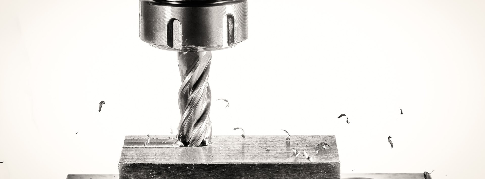
End Milling Cutters
The end milling cutter, also called an end mill, has teeth on the end as well as the periphery. The smaller end milling cutters have shanks for chuck mounting or direct spindle mounting. End milling cutters may have straight or spiral flutes. Spiral flute end milling cutters are classified as left-hand or right-hand cutters depending on the direction of rotation of the flutes.
The most common end milling cutter is the spiral flute cutter containing four flutes. Two-flute end milling cutters, sometimes referred to as two-lip end mill cutters, are used for milling slots and keyways where no drilled hole is provided for starting the cut. These cutters drill their own starting holes. Straight flute end milling cutters are generally used for milling both soft or tough materials, whilst spiral flute cutters are used mostly for cutting steel.
Large end milling cutters (normally over 2 inches in diameter) are called shell end mills and are recessed on the face to receive a screw or nut for mounting on a separate shank or mounting on an arbor, like plain milling cutters. The teeth are usually helical and the cutter is used particularly for face milling operations requiring the facing of two surfaces at right angles to each other.
T-Slot Milling Cutter
The T-slot milling cutter is used to machine T-slot grooves in worktables, fixtures, and other holding devices. The cutter has a plain or side milling cutter mounted to the end of a narrow shank. The throat of the T-slot is first milled with a side or end milling cutter and the headspace is then milled with the T-slot milling cutter.
Woodruff Keyslot Milling Cutters
The Woodruff keyslot milling cutter is made in straight, tapered-shank, and arbor-mounted types. The most common cutters of this type, under 1 1/2 inches in diameter, are provided with a shank. They have teeth on the periphery and slightly concave sides to provide clearance. These cutters are used for milling semi-cylindrical keyways in shafts.
Angle Milling Cutters
The angle milling cutter has peripheral teeth which are neither parallel nor perpendicular to the cutter axis. Common operations performed with angle cutters are cutting V-notches and serrations. Angle cutters may be single-angle milling cutters or double-angle milling cutters. The single-angle cutter contains side-cutting teeth on the flat side of the cutter. The angle of the cutter edge is usually 30°, 45°, or 60°, both right and left. Double-angle cutters have included angles of 45, 60, and 90 degrees.
Gear Hob
The gear hob is a formed tooth milling cutter with helical teeth arranged like the thread on a screw. These teeth are fluted to produce the required cutting edges. Hobs are generally used for such work as finishing spur gears, spiral gears, and worm gears. They may also be used to cut ratchets and spline shafts.
Concave and Convex Milling Cutters
Concave and convex milling cutters are formed tooth cutters shaped to produce concave and convex contours of 1/2 circle or less. The size of the cutter is specified by the diameter of the circular form the cutter produces.
Corner Rounding Milling Cutter
The corner-rounding milling cutter is a formed tooth cutter used for milling rounded corners on workpieces up to and including one-quarter of a circle. The size of the cutter is specified by the radius of the circular form the cutter produces.
Special Shaped-Formed Milling Cutter
Formed milling cutters have the advantage of being adaptable to any specific shape for special operations. The cutter is made specially for each specific job. In the field, a fly cutter is formed by grinding a single point lathe cutter bit for mounting in a bar, holder, or fly cutter arbor. The cutter can be sharpened many times without destroying its shape.
Selection of Milling Cutters
Dovetail Milling Cutters


Consider the following when choosing milling cutters:
- High-speed steel, stellite, and cemented carbide cutters have a distinct advantage of being capable of rapid production when used on a machine that can reach the proper speed.
- 45° angular cuts may either be made with a 45° single-angle milling cutter whilst the workpiece is held in a swivel vise, or with an end milling cutter whilst the workpiece is set at the required angle in a universal vise.
- The harder the material, the greater will be the heat that is generated in cutting. Cutters should be selected for their heat-resisting properties.
- Use a coarse-tooth milling cutter for roughing cuts and a finer-toothed milling cutter for light cuts and finishing operations.
- When milling stock to length, the choice of using a pair of side milling cutters to straddle the workpiece, a single-side milling cutter, or an end milling cutter will depend upon the number of pieces to be cut.
- The milling cutter should be small enough in diameter so that the pressure of the cut will not cause the workpiece to be sprung or displaced whilst being milled.
Size of Milling Cutter
In selecting a milling cutter for a particular job, choose one large enough to span the entire work surface so the job can be done with a single pass. If this cannot be done, remember that a small diameter cutter will pass over a surface in a shorter time than a large diameter cutter which is fed at the same speed.
Care and Maintenance of Milling Cutters
The life of a milling cutter can be greatly prolonged by intelligent use and proper storage. General rules for the care and maintenance of milling cutters are given below:
- New cutters received from stock are usually wrapped in oil paper which should not be removed until the cutter is used.
- Take care to operate the machine at the proper speed for the cutter being used, as excessive speed will cause the cutter to wear rapidly from overheating.
- Take care to prevent the cutter from striking the hard jaws of the vise, chuck, clamping bolts, or nuts.
- Whenever practical, use the proper cutting oil on the cutter and workpiece during operations, since lubrication helps prevent overheating and cutter wear.
- Keep cutters sharp. Dull cutters require more power to drive and this power, being transformed into heat, softens the cutting edges. Dull cutters should be marked as such and set aside for grinding.
- Thoroughly clean and lightly coat milling cutters with oil before storing.
- Place cutters in drawers or bins so that their cutting edges will not strike each other. Hang small cutters on hooks or pegs, and set large cutters on end. Place taper and straight shank cutters in separate drawers, bins, or racks provided with suitable sized holes to receive the shanks.
- Never operate a cutter backwards. Due to the clearance angle, the cutter will rub, producing a great deal of friction. Operating the cutter backward may result in cutter breakage.
At Adendorff Machinery Mart, you'll find a comprehensive range of high-quality milling cutters and accessories to maintain your equipment.
Arbors
Milling machine arbors are made in various lengths and in standard diameters of 7/8, 1, 1 1/4, and 1 1/2 inch. The shank is made to fit the taper hole in the spindle whilst the other end is threaded.
NOTE: The threaded end may have left or right-handed threads.
The milling machine spindle may be self-holding or self-releasing. The self-holding taper is held in the spindle by the high wedging force. The spindle taper in most milling machines is self-releasing; tooling must be held in place by a draw bolt extending through the centre of the spindle.
Arbors are supplied with one of three tapers to fit the milling machine spindle: the Standard Milling Machine taper, the standard taper, and the taper with tang. The Standard Milling Machine Taper is used on most machines of recent manufacture. These tapers are identified by the number 30, 40, 50, or 60. Number 50 is the most commonly used size on all modern machines.
Standard Milling Machine Arbor
The standard milling machine arbor has a tapered, cylindrical shaft with a standard milling taper on the driving end and a threaded portion on the opposite end to receive the arbor nut. One or more milling cutters may be placed on the straight cylindrical portion of the arbor and held in position by sleeves and the arbor nut. The standard milling machine arbor is usually splined and keys are used to lock each cutter to the arbor shaft. These arbors are supplied in three styles, various lengths and standard diameters.
The most common way to fasten the arbor in the milling machine spindle is to use a draw bar. The bar threads into the taper shank of the arbor to draw the taper into the spindle and hold it in place. Arbors secured in this manner are removed by backing out the draw bar and tapping the end of the bar to loosen the taper.
The end of the arbor opposite the taper is supported by the arbor supports of the milling machine. One or more supports are used depending on the length of the arbor and the degree of rigidity required. The end may be supported by a lathe centre bearing against the arbor nut or by a bearing surface of the arbor fitting inside a bushing of the arbor support.
The arbor may also be firmly supported as it turns in the arbor support bearing suspended from the over-arm.
Style A
Style A has a cylindrical pilot on the end that runs in a bronze bearing in the arbor support. This style is mostly used on small milling machines or when maximum arbor support clearance is required.
Style B
Style B is characterised by one or more bearing collars that can be positioned to any part of the arbor. This allows the bearing support to be positioned close to the cutter, to obtain rigid setups in heavy duty milling operations.
Style C
Style C arbors are used to mount the smaller size milling cutters, such as end mills that cannot be bolted directly on the spindle nose. Use the shortest arbor possible for the work.
Screw Arbor
Screw arbors are used to hold small cutters that have threaded holes. These arbors have a taper next to the threaded portion to provide alignment and support for tools that require a nut to hold them against a taper surface. A right-hand threaded arbor must be used for right-hand cutters whilst a left-hand threaded arbor is used to mount left-hand cutters.
The slitting saw milling cutter arbor is a short arbor having two flanges between which the milling cutter is secured by tightening a clamping nut. This arbor is used to hold metal slitting saw milling cutters used for slotting, slitting, and sawing operations.
The shell end milling cutter arbor has a bore in the end in which shell end milling cutters fit and are locked in place by means of a cap screw.
The fly cutter arbor is used to support a single-edge lathe, shaper, or planer cutter bit for boring and gear cutting operations on the milling machine.
Collets, Spindle Adapters, and Quick-Change Tooling
Description
Milling cutters that contain their own straight or tapered threaded portion to provide alignment and support for tools shanks are mounted to the milling machine spindle with collets, spindle adapters, and quick-change tooling which adapts the cutter shank to the spindle.
Collets
A collet is a form of a sleeve bushing for reducing the size of the hole in the milling machine spindle so that small shank tools can be fitted into large spindle recesses. They are made in several forms, similar to drilling machine sockets and sleeves, except that their tapers are not alike.
Spindle Adapters
A spindle adapter is a form of a collet having a standardised spindle end. They are available in a wide variety of sizes to accept cutters that cannot be mounted on arbors. They are made with either the Morse taper shank or the standard taper with tang having a standard spindle end.
Chuck Adapter
A chuck adapter is used to attach chucks to milling machines having a standard spindle end. The collet holder is sometimes referred to as a collet chuck. Various forms of chucks can be fitted to milling machine spindles for holding drills, reamers, and small cutters for special operations.
Quick-Change Tooling
The quick-change adapter mounted on the spindle nose is used to speed up tool changing. Tool changing with this system allows you to set up a number of milling operations such as drilling, end milling, and boring without changing the setup of the part being machined. The tool holders are mounted and removed from a master holder mounted to the machine spindle by means of a clamping ring.
Vises
Either a plain or swivel-type vise is furnished with each milling machine. The plain vise, similar to the machine table vise, is used for milling straight workpieces and is bolted to the milling machine table either at right angles or parallel to the machine arbor. The swivel vise can be rotated and contains a scale graduated in degrees at its base to facilitate milling workpieces at any angle on a horizontal plane.
The universal vise, which may be obtained as extra equipment, is designed so that it can be set at both horizontal and vertical angles. This type of vise may be used for flat and angular milling. The all-steel vise is the strongest setup because the workpiece is clamped closer to the table. The vise can securely fasten castings, forgings, and rough-surfaced workpieces. The jaw can be positioned in any notch on the two bars to accommodate different shapes and sizes.
The air or hydraulically operated vise is used more often in production work. This type of vise eliminates tightening by striking the crank with a lead hammer or other soft face hammer.
Mounting and Indexing Work
An efficient and positive method of holding workpieces to the milling machine table is important if the machine tool is to be used to its fullest advantage. The most common methods of holding are clamping a workpiece to the table, clamping a workpiece to the angle plate, clamping the workpiece in fixtures, holding a workpiece between centres, holding the workpiece in a chuck, and holding the workpiece in a vise.
Regardless of the method used in holding, there are certain factors that should be observed in every case. The workpiece must not be sprung in clamping, it must be secured to prevent it from springing or moving away from the cutter, and it must be so aligned that it may be correctly machined.
T-Slots
Milling machine worktables are provided with several T-slots which are used either for clamping and locating the workpiece itself or for mounting the various holding devices and attachments. These T-slots extend the length of the table and are parallel to its line of travel. Most milling machine attachments, such as vises and index fixtures, have keys or tongues on the underside of their bases so that they may be located correctly in relation to the T-slots.
Methods of Mounting Workpieces
Clamping Workpieces to the Table
When clamping a workpiece to the worktable of the milling machine, the table and the workpiece should be free from dirt and burrs. Workpieces having smooth machined surfaces may be clamped directly to the table, provided the cutter does not come in contact with the table surface during milling. When clamping workpieces with unfinished surfaces in this way, the table face should be protected from damage by using a shim under the workpiece. Paper, plywood, and sheet metal are shim materials.
Clamps should be located on both sides of the workpiece if possible to give a full bearing surface. These clamps are held by T-slot bolts inserted in the T-slots of the table. Clamp supports must be the same height as the workpiece. Never use clamp supports that are lower than the workpiece. Adjustable step blocks are extremely useful to raise the clamps, as the height of the clamp bar may be adjusted to ensure maximum clamping pressure. Clamping bolts should be placed as near to the workpiece as possible so that the full advantage of the fulcrum principle may be obtained.
Clamping a Workpiece to the Angle Plate
Workpieces clamped to the angle plate may be machined with surfaces parallel, perpendicular, or at an angle to a given surface. When using this method of holding a workpiece, precautions should be taken similar to those mentioned for clamping work directly to the table. Angle plates are either adjustable or non-adjustable and are generally held in alignment by keys or tongues that fit into the table T-slots.
Clamping Workpieces in Fixtures
Fixtures are generally used in production work where a number of identical pieces are to be machined. The design of the fixture depends upon the shape of the piece and the operations to be performed. Fixtures are always constructed to secure maximum clamping surfaces and are built to use a minimum number of clamps or bolts in order to reduce the setup time required. Fixtures should always be provided with keys to assure positive alignment with the table T-slots.
Holding Workpieces Between Centres
The indexing fixture is used to support workpieces which are centred on both ends. When the piece has been previously reamed or bored, it may be pressed upon a mandrel and then mounted between the centres.
Two types of mandrels may be used for mounting workpieces between centres. The solid mandrel is satisfactory for many operations, whilst one having a shank tapered to fit into the index head spindle is preferred in certain cases.
A jackscrew is used to prevent springing of long slender workpieces held between centres or workpieces that extend some distance from the chuck.
Workpieces mounted between centres are fixed to the index head spindle by means of a lathe dog. The bent tail of the dog should be fastened between the setscrews provided in the driving centre clamp in such a manner as to avoid backlash and prevent springing the mandrel.
Holding Workpieces in a Chuck
Before screwing the chuck to the index head spindle, it should be cleaned and any burrs on the spindle or chuck removed. Burrs may be removed with a smooth-cut, three cornered file or scraper. The chuck should not be tightened on the spindle so tightly that a wrench or bar is required to remove it. Cylindrical workpieces held in the universal chuck may be checked for trueness by using a test indicator mounted upon a base resting upon the milling machine table.
Holding Workpieces in the Vise
Five types of vises are manufactured in various sizes for holding milling machine workpieces. These vises have locating keys or tongues on the underside of their bases so they may be located correctly in relation to the T-slots on the milling machine table.
The plain vise similar to the machine table vise is fastened to the milling machine table. Alignment with the milling machine table is provided by two slots at right angles to each other on the underside of the vise. These slots are fitted with removable keys that align the vise with the table T-slots either parallel to the machine arbor or perpendicular to the arbor.
The swivel vise can be rotated and contains a scale graduated in degrees at its base which is fastened to the milling machine table and located by means of keys placed in the T-slots. By loosening the bolts which clamp the vise to its graduated base, the vise may be moved to hold the workpiece at any angle in a horizontal plane.
When rough or unfinished workpieces are to be vise mounted, a piece of protecting material should be placed between the vise and the workpiece to eliminate marring by the vise jaws. When it is necessary to position a workpiece above the vise jaws, parallels of the same size and of the proper height should be used. These parallels should only be high enough to allow the required cut, as excessive raising reduces the holding ability of the jaws.
Indexing
Indexing is the process of evenly dividing the circumference of a circular workpiece into equally spaced divisions, such as in cutting gear teeth, cutting splines, milling grooves in reamers and taps, and spacing holes on a circle. The index head of the indexing fixture is used for this purpose.
Index Head
The index head of the indexing fixture contains an indexing mechanism which is used to control the rotation of the index head spindle to space or divide a workpiece accurately. A simple indexing mechanism consists of a 40-tooth worm wheel fastened to the index head spindle, a single-cut worm, a crank for turning the wormshaft, and an index plate and sector.
Since there are 40 teeth in the worm wheel, one turn of the index crank causes the worm, and consequently, the index head spindle to make 1/40 of a turn; so 40 turns of the index crank revolve the spindle one full turn.
Index Plate
The indexing plate is a round plate with a series of six or more circles of equally spaced holes; the index pin on the crank can be inserted in any hole in any circle. With the interchangeable plates regularly furnished with most index heads, the spacing necessary for most gears, boltheads, milling cutters, splines, and so forth can be obtained.
Plain Indexing
The following principles apply to basic indexing of workpieces:
Suppose it is desired to mill a project with eight equally spaced teeth. Since 40 turns of the index crank will turn the spindle one full turn, 1/8th of 40 or 5 turns of the crank after each cut will space the gear for 8 teeth. If it is desired to space equally for 10 teeth, 1/10 of 40 or 4 turns would produce the correct spacing.
The same principle applies whether or not the divisions required divide equally into 40. For example, if it is desired to index for 6 divisions, 6 divided into 40 equals 6 2/3 turns; similarly, to index for 14 spaces, 14 divided into 40 equals 2 6/7 turns.
Rule: To determine the number of turns of the index crank needed to obtain one division of any number of equal divisions on the workpiece, divide 40 by the number of equal divisions desired (provided the worm wheel has 40 teeth, which is standard practice).
Direct Indexing
The construction of some index heads permits the worm to be disengaged from the worm wheel, making possible a quicker method of indexing called direct indexing. Direct indexing is accomplished by an additional index plate fastened to the index head spindle. A stationary plunger in the index head fits the holes in this index plate. By moving this plate by hand to index directly, the spindle and the workpiece rotate an equal distance. Direct index plates usually have 24 holes and offer a quick means of milling squares, hexagons, taps, and so forth. Any number of divisions which is a factor of 24 can be indexed quickly and conveniently by the direct indexing method.
Indexing in Degrees
Workpieces can be indexed in degrees as well as fractions of a turn with the usual index head. There are 360 degrees in a complete circle and one turn of the index crank revolves the spindle 1/40 or 9 degrees. Therefore, 1/9 turn of the crank rotates the spindle 1 degree. Workpieces can therefore be indexed in degrees by using a circle of holes divisible by 9.
General Milling Operations
Setup
The success of any milling operation depends, to a great extent, upon judgement in setting up the job, selecting the proper milling cutter, and holding the cutter by the best means under the circumstances. Some fundamental practices have been proved by experience to be necessary for good results on all jobs.
- Before setting up a job, be sure that the workpiece, table, the taper in the spindle, and the arbor or cutter shank are free from chips, nicks, or burrs.
- Do not select a milling cutter of larger diameter than is necessary.
- Check the machine to see if it is in good running order and properly lubricated, and that it moves freely, but not too freely in all directions.
- Consider direction of rotation. Many cutters can be reversed on the arbor, so be sure you know whether the spindle is to rotate clockwise or counter-clockwise.
- Feed the workpiece in a direction opposite the rotation of the milling cutter (conventional milling).
- Do not change feeds or speeds whilst the milling machine is in operation.
- When using clamps to secure a workpiece, be sure that they are tight and that the piece is held so it will not spring or vibrate under cut.
- Use a recommended cutting oil liberally.
- Use good judgement and common sense in planning every job, and profit from previous mistakes.
- Set up every job as close to the milling machine spindle as circumstances will permit.
Milling Operations
Milling operations may be classified under four general headings as follows:
- Face milling: Machining flat surfaces which are at right angles to the axis of the cutter.
- Plain or slab milling: Machining flat surfaces which are parallel to the axis of the cutter.
- Angular milling: Machining flat surfaces which are at an inclination to the axis of the cutter.
- Form milling: Machining surfaces having an irregular outline.
Special Operations
Explanatory names, such as sawing, slotting, gear cutting, and so forth have been given to special operations. Routing is a term applied to milling an irregular outline whilst controlling the workpiece movement by hand feed. Grooving reamers and taps is called fluting. Gang milling is the term applied to an operation in which two or more milling cutters are used together on one arbor. Straddle milling is the term given to an operation in which two milling cutters are used to straddle the workpiece and mill both sides at the same time.
Speeds for Milling Cutters
The speed of milling is the distance in FPM (feet per minute) at which the circumference of the cutter passes over the work. The spindle RPM necessary to give a desired peripheral speed depends on the size of the milling cutter. The best speed is determined by the kind of material being cut and the size and type of cutter used, width and depth of cut, finish required, type of cutting fluid and method of application, and power and speed available are factors relating to cutter speed.
Factors Governing Speed
There are no hard and fast rules governing the speed of milling cutters; experience has shown that the following factors must be considered in regulating speed:
- A metal slitting saw milling cutter can be rotated faster than a plain milling cutter having a broad face.
- Cutters having undercut teeth (positive rake) cut more freely than those having radial teeth (without rake); hence, they may run at higher speeds.
- Angle cutters must be run at slower speeds than plain or side cutters.
- Cutters with inserted teeth generally will stand as much speed as a solid cutter.
- A sharp cutter may be operated at greater speeds than a dull one.
- A plentiful supply of cutting oil will permit the cutter to run at higher speeds than without cutting oil.
Selecting Proper Cutting Speeds
If the operator finds that the machine, the milling cutter, or the workpiece cannot be handled suitably at recommended speeds, immediate readjustments should be made. If carbon steel cutters are used, the speed should be about one-half the recommended speed for high-speed steel cutters. If carbide-tipped cutters are used, the speed can be doubled.
If a plentiful supply of cutting oil is applied to the milling cutter and the workpiece, speeds can be increased 50 to 100 percent. For roughing cuts, a moderate speed and coarse feed often give best results; for finishing cuts, the best practice is to reverse these conditions, using a higher speed and lighter feed.
Speed Computation
The formula for calculating spindle speed in revolutions per minute is as follows:
RPM = (CS × 4) / D
Where:
- RPM = Spindle speed (in revolutions per minute)
- CS = Cutting speed of milling cutter (in SFPM - surface feet per minute)
- D = Diameter of milling cutter (in inches)
Example: The spindle speed for machining a piece of steel at a speed of 35 SFPM with a cutter 2 inches in diameter is calculated as follows:
RPM = (CS × 4) / D = (35 × 4) / 2 = 140 / 2 = 70 RPM
Therefore, the milling machine spindle would be set for as near 70 RPM as possible.
Feeds for Milling
Auto / Power Feed Units


The rate of feed, or the speed at which the workpiece passes the cutter, determines the time required for cutting a job. In selecting the feed, there are several factors which should be considered.
Forces are exerted against the workpiece, the cutter, and their holding devices during the cutting process. The force exerted varies directly with the amount of feed and depth of cut, and in turn are dependent upon the rigidity and power of the machine. Milling machines are limited by the power they can develop to turn the cutter and the amount of vibration they can resist when using coarse feeds and deep cuts.
The feed and depth of the cut also depend upon the type of milling cutter being used. For example, deep cuts or coarse feeds should not be attempted when using a small diameter end milling cutter. Coarse cutters with strong cutting teeth can be fed at a faster rate because the chips may be washed out more easily by the cutting oil.
Experience and judgement are extremely valuable in selecting the correct milling feeds. Feeds are governed by many variable factors, such as the degree of finish required. Using a coarse feed, the metal is removed more rapidly but the appearance and accuracy of the surface produced may not reach the standard desired for the finished product. Because of this fact, finer feeds and increased speeds are used for finer, more accurate finishes, whilst for roughing, use a comparatively low speed and heavy feed.
Designation of Feed
The feed of the milling machine may be designated in inches per minute or millimetres per minute. The milling feed is determined by multiplying the chip size (chip per tooth) desired, the number of teeth on the cutter, and the revolutions per minute of the cutter.
IPM = CPT × N × RPM
Where:
- IPM = Feed rate in inches per minute
- CPT = Chip per tooth
- N = Number of teeth per minute of the milling cutter
- RPM = Revolutions per minute
Example:
First step - calculate the spindle speed:
RPM = (CSD × 4) / D = (300 × 4) / (1/2) = 1,200 / 0.5 = 2,400 RPM
Second step - calculate the feed rate:
IPM = CPT × N × RPM = 0.005 × 2 × 2,400 = 24
Therefore, the RPM for a 1/2-inch-diameter end mill machining aluminium revolves at 2,400 RPM and the feed rate should be 24 inches per minute.
Direction of Feed
It is usually regarded as standard practice to feed the workpiece against the milling cutter. When the workpiece is fed against the milling cutter, the teeth cut under any scale on the workpiece surface and any backlash in the feed screw is taken up by the force of the cut.
As an exception to this recommendation, it is advisable to feed with the milling cutter when cutting off stock or when milling comparatively deep or long slots.
The direction of cutter rotation is related to the manner in which the workpiece is held. The cutter should rotate so that the piece springs away from the cutter; then there will be no tendency for the force of the cut to loosen the piece. No milling cutter should ever be rotated backward; this will break the teeth.
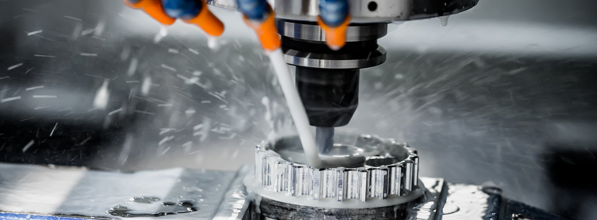
Cutting Oils
The major advantage of using a coolant or cutting oil is that it dissipates heat, giving longer life to the cutting edges of the teeth. The oil also lubricates the cutter face and flushes away the chips, consequently reducing the possibility of marring the finish.
Types
Cutting oils are basically water-based soluble oils, petroleum oils, and synthetic oils. Water-based coolants have excellent heat transfer qualities; other oils result in good surface finishes. In general, a simple coolant is all that is required for roughing. Finishing requires a cutting oil with good lubricating properties to help produce a good finish on the workpiece. Plastics and cast iron are almost always machined dry.
Method of Use
The cutting oil or coolant should be directed by means of coolant drip can, pump system, or coolant mist mix to the point where the cutter contacts the workpiece. Regardless of method used, the cutting oil should be allowed to flow freely over the workpiece and cutter.
Keyway Milling
Keyways are grooves of different shapes cut along the axis of the cylindrical surface of shafts, into which keys are fitted to provide a positive method of locating and driving members on the shafts. A keyway is also machined in the mounted member to receive the key.
The type of key and corresponding keyway to be used depends upon the class of work for which it is intended. The most commonly used types of keys are the Woodruff key, the square-ends machine key, and the round-end machine key.
Woodruff Key
The Woodruff keys are semi-cylindrical in shape and are manufactured in various diameters and widths. The circular side of the key is seated into a keyway which is milled in the shaft. The upper portion fits into a slot in a mating part, such as a pulley or gear.
Woodruff key sizes are designated by a code number in eighths of an inch, and the digits preceding the last two digits give the width of the key in thirty-seconds of an inch. Thus, a number 204 Woodruff key would be 4/8 or 1/2 inch in diameter and 2/32 or 1/16 inch wide, whilst a number 1012 Woodruff key would be 12/8 or 1 1/2 inches in diameter and 10/32 or 5/16 inch wide.
Square-End Machine Key
Square-ends machine keys are square or rectangular in section and several times as long as they are wide. For the purpose of interchangeability and standardisation, these keys are usually proportioned with relation to the shaft diameter in the following method:
- Key width equals approximately one-quarter of the shaft diameter.
- Key thickness for rectangular section keys (flat keys) equals approximately 1/6 of the shaft diameter.
- Minimum length of the key equals 1 1/2 times the shaft diameter.
- Depth of the keyway for square section keys is 1/2 the width of the key.
- Depth of the keyway for rectangular section keys (flat keys) is 1/2 the thickness of the key.
Milling Cutters Used for Milling Keyways
Shaft keyways for Woodruff keys are milled with Woodruff keyslot milling cutters. The Woodruff keyslot milling cutters are numbered by the same system employed for identifying Woodruff keys. Thus, a number 204 Woodruff keyslot cutter has the proper diameter and width for milling a keyway to fit a number 204 Woodruff key.
Square-end keyways can be cut with a plain milling cutter or side milling cutter of the proper width for the key. Round-end keyways must be milled with end milling cutters so that the rounded end or ends of the key may fit the ends of the keyway. The cutter should be equal in diameter to the width of the key.
Additional Operations
T-Slot Milling
Cutting T-slots in a workpiece holding device is a typical milling operation. The size of the T-slots depends upon the size of the T-slot bolts which will be used. Two milling cutters are required for milling T-slots: a T-slot milling cutter and either a side milling cutter or an end milling cutter.
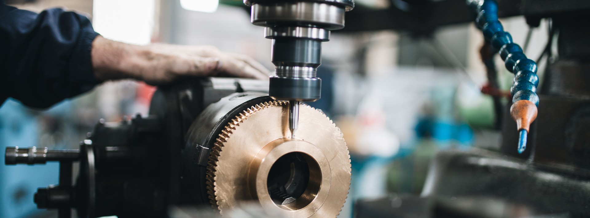
Gear Cutting
Gear teeth are cut on the milling machine using formed milling cutters called involute gear cutters. These cutters are manufactured in many pitch sizes and shapes for different numbers of teeth per gear.
Drilling and Boring
The milling machine may be used effectively for drilling, since accurate location of the hole may be secured by means of the feed screw graduations. Various types of boring tool holders may be used for boring on the milling machine.
At Adendorff Machinery Mart, we stock a comprehensive range of milling machines, cutters, accessories, and tooling to ensure you have everything needed for professional milling operations. Visit your nearest Adendorff branch or browse our website for expert advice and quality machinery at competitive prices.