ELATHE500 Precision Bench Lathe: Operation Manual Guide
ELATHE500 Precision Bench Lathe: Operation Manual Guide
Looking for a precision bench lathe that delivers professional capabilities in a compact package? The ELATHE500 is a 140kg precision machine tool designed for serious hobbyists, small workshops, and model engineers who need accurate turning capabilities without industrial floor space requirements.
This guide presents the complete operation manual for the ELATHE500 Precision Bench Lathe, covering everything from initial assembly and specifications to maintenance procedures and parts identification. Whether you're commissioning your new machine or need reference material for daily operation, this manual contains the essential information to operate your lathe safely and maintain its precision for years to come.
What You'll Learn in This Manual
Machine Overview
The ELATHE500 is a CE-certified precision bench lathe featuring a 550W motor, six spindle speeds, and comprehensive threading capabilities. With a 110mm swing over bed and 350mm between centers, it handles a wide range of turning operations while maintaining the compact footprint essential for small workshops.
Machine Specifications
| Specification | Value |
|---|---|
| Model | BV20-BL |
| Motor | 230V a.c. 550W |
| Maximum swing over the bed | 110mm |
| Maximum distance between centers | 350mm |
| Spindle Speeds (Forward and Backward) | 170, 312, 450, 736, 1354, 1950 RPM |
| Reversing Method | Electrical |
| Clear Bore in Headstock Mandrel | 20mm |
| Possible metric thread pitches | 17 |
| Possible imperial threads | 17 |
| Number of possible feed speeds | 5 |
| Maximum longitudinal travel of compound rest | 70mm |
| Maximum traverse travel of compound rest | 115mm |
| Maximum turning angle of compound rest | + or – 45 degree |
| Maximum extension of tailstock barrel | 50mm |
| Leadscrew Gearbox ratio | 6:1 |
| Weight | 140Kg |
| Overall size (Lathe only) | 1050 x 615 x 560mm |
Definitions
Main Axis: This is the axis established through the spindle of the headstock. It is horizontal to and parallel with the lathe bed along its length.
Work Axis: This is the axis established by the work piece, it is horizontal to but not necessarily parallel with, the lathe bed, along its length.
Traverse Axis: This is the axis described by the traverse slide when it is being moved independently of the saddle. It is perpendicular to the main axis in the horizontal plane.
Compound Axis: This is the axis described by the compound slide when it is being operated independently of the traverse slide and the saddle.
Assembly Instructions
Unpacking and Cleaning
Having unpacked your machine and its accessories, please check the contents against the equipment list "What's in the box". If there are any discrepancies, please contact us using the procedures laid down in the catalogue. Please dispose of the packaging responsibly, much of the material is bio-degradable.
The machine and its accessories will arrive coated with heavy corrosion preventative grease. This will need to be cleaned from the machine, its components and accessories prior to its being set up and commissioned. Use coal oil, paraffin or a proprietary degreaser to remove the barrier grease. Be warned, it will stain if you splash it on clothing etc., wear overalls et al., rubber gloves are also a good idea, as is eye protection if your cleaning process tends to be a little bit enthusiastic. After cleaning, lightly coat the machine with a thin layer of light machine oil. N.B if you used paraffin/kerosene make sure you apply this thin film sooner rather than later.
Please read the instruction Manual prior to using your new machine; as well as the installation procedure, there are daily and periodic maintenance recommendations to help you keep your machine on top line and prolong its life. Keep this instruction Manual readily accessible for any other who may also be required to use the machine.
Mounting Requirements
The ELATHE500 requires to be mounted on a rigid bed, this is to ensure stability of the machine and to attenuate any vibration that is generated when the machine is running, (especially with eccentric work mounted in the chuck).
The bed should be flat and set level in both planes, and at a height that enables comfortable operation of the machine. It is not necessary to anchor the bed through to the floor, but it must be stable enough to remain immovable during any normal forceful operations (especially tightening) carried out whilst operating your lathe.
If you are preparing your own bed for the machine, it should be at least 870mm long by 320mm wide, you will need to drill two 14mm holes to allow for bolt fixing. Set out the centers of the holes as follows—sizes are minimum excepting distance between centers:
- From the left side of the bed (Headstock side) 170mm, 150mm from the front edge of the bed
- Distance between centers 650mm; second hole again 150mm from front edge
- Bolt the lathe to the bed using M12 nuts, bolts and washers.
Initial Oil Fill
Once the lathe is mounted, remove the headstock cover plate and fill the headstock with SAE20 oil to a level slightly above the sight glass. Do not overfill. The gearbox does not have oil sealed bearing fitted throughout, and if you overfill oil will leak out.
Pre-Start Checks
The machine was fully greased and oiled before leaving the factory, but it would certainly be prudent for you to check and re-oil all the lubrication points and lube all the beds/slides etc., before start up. Refer to the lubrication chart later in this manual.
Check the tension of the drive belt. If the belt is too slack, tighten by adjusting the motor mounting plate, ensuring that you maintain co-linearity of the two pulleys.
Running-In Procedure
Although the machine has been thoroughly tested at the factory, it is recommended that you carry out a "running in" procedure to check for correct gear meshing, vibration, etc.:
- Ensure the lathe is running "forward" (i.e. the spindle is turning towards you)
- Select the lowest spindle speed i.e. 170rpm, and run for approximately 20 minutes
- Check for vibration, excessive noise, etc.
- After the 20min period, increase the speed one step at a time and run for approximately 5 minutes in each gear
- Stop the machine before changing gear
- If everything appears satisfactory, reduce the speed to one of the lower registers; manually drive the saddle back towards the tailstock, check the saddle feed engages positively; engage the saddle feed and drive the saddle toward the headstock, checking for smoothness of movement, etc. Engage and disengage the saddle several times during its travel and check that its travel pick up is smooth.
- If everything appears to be satisfactory, move the saddle to a position about mid travel, MAKE SURE THE SPINDLE IS STOPPED, switch the machine into reverse and check the machine functions equally well whilst running in reverse.
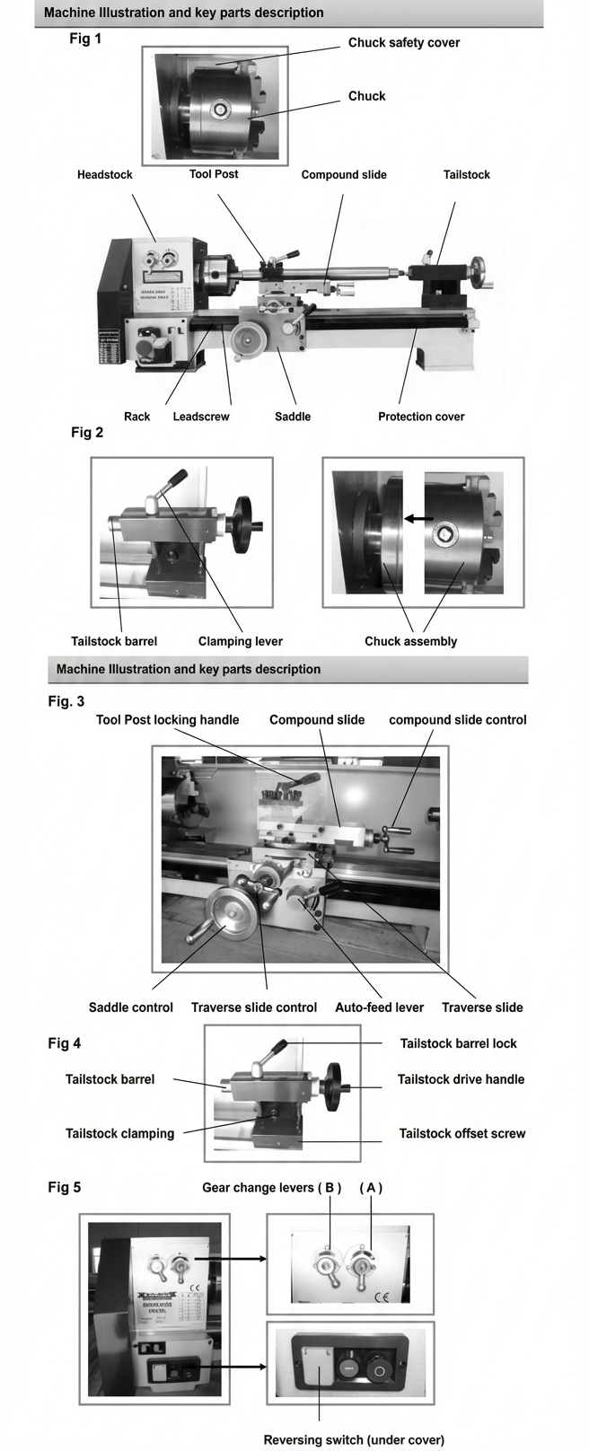
Identification and Description of Parts
Headstock
The 'engine block' of the lathe, supports the motor, the spindle, contains the gearbox for the spindle speed selection, mount the change gears and the driven end of the lead screw.
Rack (unseen)
The rack is fixed on the underside of the front rail of the lathe bed, it is permanently engaged with the saddle control wheel pinion.
Tailstock
Large casting that mounts the tailstock barrel, it is moved on and clamped to the lathe bed to allow the tailstock barrel to be moved to the proximity of the work piece. It can be offset from the central axis of the lathe to allow for taper turning between centers.
Lead screw / Rack guard
A formed metal plate that covers and protects the leadscrew and the rack.
Tool Post
A four sided tool post. Each tool position has 3 securing bolts to clamp the tool in place. The tool post is located on a central pivot mounted on the top of the compound slide. It has a four position 'click' locator, that locates it to its major axis, but it can be held at any angle by the tool post locking clamp.
Leadscrew (unseen)
The leadscrew, through the various gear trains available, rotates at a selected ratio to the spindle to enable the various screw threads to be cut, or to provide a feed rate for the saddle when auto feed is selected.
Chuck Safety Cover
A clear acetate cover mounted on a pivot bar on the rear top front face of the headstock, it can be tipped out of the way to access the chuck when it is stationary, and repositioned over the chuck during operation.
Tool post cover
Fitted to compound slide it is there to provide protection from "flying swarf" whilst turning between centers.
Motor
Single phase 230V 50Hz motor. 1H.P.
Chuck mounting back plate
The chuck mounting flanges is integral with the spindle and mounts all the material carriers, (chucks, faceplate etc.), it is bored with a No.3 Morse taper to accept the headstock centre. The boring is then carried through the complete length of the spindle (20mm clear) to allow long lengths of round bar to be machined. Because of the limited space between the headstock and the chuck mounting flange a shortened Allen key has been supplied to allow tightening of the chuck securing bolts.
Tailstock barrel lock
Small 'swing' lever that locks the barrel in place once it has been moved into the required position.
Tailstock drive handle
This engineer's wheel and handle controls the movement of the tailstock barrel, backwards and forward. It has a graduated ring (thimble) mounted on the neck of the handle so that the amount of movement can be monitored.
Tailstock barrel
Steel barrel bored with No.2 Morse taper to mount various tooling, centers, drill chuck, reamers etc. the barrel has a travel of 50mm, this travel allows the mounted tool or centre to be brought into controlled contact with the work.
Mounting feet
Shaped in the casting of the lathe bed, the two feet have 14mm slots cut into them to enable the fitting of two 12mm bolts to effect the rigid fastening of lathe onto its stand.
Lathe bed
V rail and flat rail bed, precision machined to provide an accurate mounting for the headstock and a precision guide for the movement of the saddle. It also mounts the tailstock in an accurate relationship to the main axis of the lathe.
Saddle
Main casting that is precision machined to marry with the lathe bed. It moves parallel to the main axis. It mounts the traverse slide. It also mounts its control handle and the auto feed or thread cutting engaging lever.
Saddle control
This engineers wheel/control handle is mounted on a shaft that goes through the apron of the saddle; there is a pinion mounted on the end of shaft that is permanently engaged with the fixed rack on the lathe bed. This enables the saddle to be moved back and forth along the lathe bed. N.B. Remember this handle is PERMANENTLY engaged to the rack and during thread cutting or auto feeding will turn with the movement of the saddle.
Auto feed lever
This lever engages the saddle to the leadscrew to enable the auto feed or the thread cutting function of the lathe. Move the lever down to engage the feed. As there is no synchronising dial indicator fitted for thread cutting—to ensure correct "pick-up" during thread cutting, leave the auto feed lever engaged. Disengage the tool clear of the work. Stop the spindle, electrically reverse the drive system and drive tool back clear of the working piece—stop the spindle: switch back to normal—and set the new cutting depth and restart the machine; repeat this procedure until the thread is cut.
Traverse slide
Mounted on a 'V' machined slide on the saddle. The accuracy of the fit of the 'V' slide is maintained by the 'gybe' strips set in the offside of the traverse slide.
Traverse slide control handle
A 'U' handle, mounted on a shaft that is anchored into a housing cast at the front of the traverse slide, the shaft is threaded and is engaged in a fixed thread follower on the slide, enabling the traverse slide to be driven back and forth across the saddle perpendicular to the main axis. There is a graduated ring (thimble) on the neck of the handle to allow the movement of the slide to be measured.
Compound slide
The compound slide is mounted on a machined 'V' slide with a circular base, that is then mounted and located on the top of the traverse slide by a central pivot. Through the circular block, near the edge, are two diametrically opposed nuts and bolts; the bolt shanks extend through two concentric slots machined in the traverse slide that allow the compound slide mount to turn about the central pivot. The nuts on the ends of the bolts (in machined recesses under the front and back edge of the slide) also lock the compound slide along its selected axis (+ or – 45 degrees from the main axis).
The compound slide fits over this 'vee' slide mount; the accuracy of the fit is maintained by the 'gybe' strips set in the front edge of the compound slide. There is a scale set on the front of the circular base to enable the angle set on the compound slide to be measured.
Compound slide control handle
A 'U' handle, mounted on a shaft that is anchored into a housing cast at the Control Handle end of the slide; the shaft is threaded and is engaged in a fixed thread follower on the circular mounting plate, enabling the slide to be driven backward and forward along its axis. There is a graduated ring (thimble) on the neck of the handle to allow the movement of the slide to be measured.
Tool post locking handle
The central locating pivot for the tool post has a threaded end which passes through the tool post, and is fitted with a threaded boss lever handle. Tightening down on the handle clamps the tool post firmly in position.
Tailstock clamp
A nut and bolt fitted through the tailstock and clamping dog. Tightening the nut pulls the clamping clog up against the underside of the bed and clamps the tailstock in position. Conversely, loosening the nut releases the bolt and the clamp allowing the tailstock to slide freely on the bed.
Tailstock offset screws
The tailstock is keyed into a large support base, and is able to be driven backwards and forward across this base about the central axis of the lathe. There are two opposing screws set in the base that control the movement of tailstock, the screws have to be adjusted sequentially, i.e. loosen, tighten, loosen, tighten, etc., to move the tailstock.
Gear change levers
Two levers marked "A" and "B" which, in their setting select the different spindle speeds of the lathe. Refer to the Speed change chart to select the required speed.
On and off switches
Green push button switch marked 'I' to start the motor, red push button switch marked 'O' to switch the motor off.
Feed speed and thread cutting gear change chart
This chart indicates the necessary gears and their positions to enable the wide range of metric, imperial, module and diameter threads to be cut and the different feed rate to be achieved. The feed speed is quoted as a linear distance along the Main Axis per revolution of the leadscrew.
Reversing switch
Rocker switch set under a protective cover, (to prevent inadvertent operation), changing the position of the switch will reverse the direction of the motor. MAKE SURE THE SPINDLE IS STOPPED BEFORE OPERATING THIS SWITCH.
Spindle speed change chart
This indicates the position of the levers to select the various spindle speeds.
Headstock Components
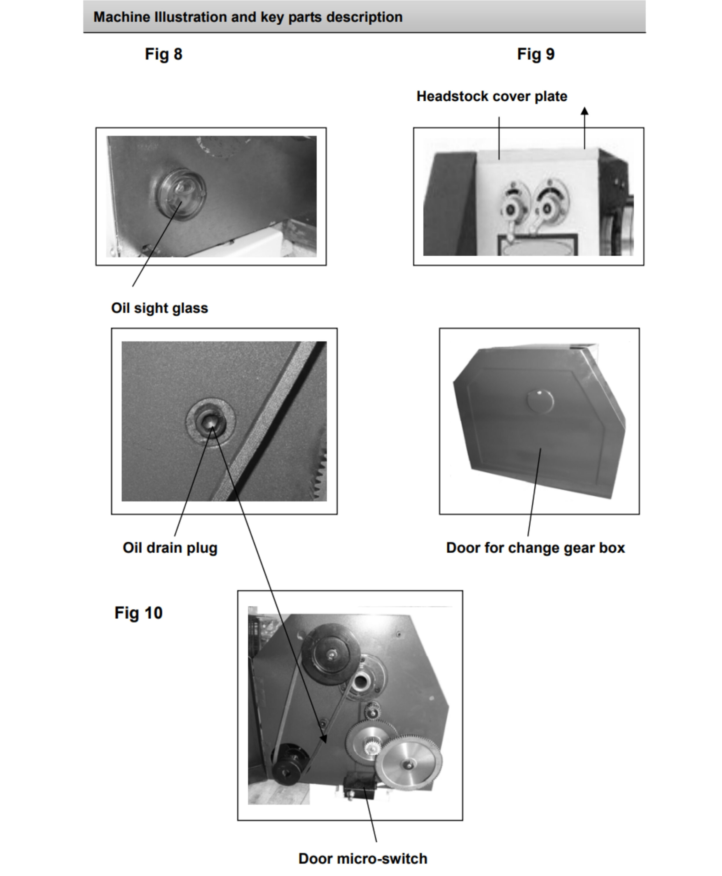
Door for change gear compartment
Protective cover, enclosing the motor pulley, the drive pulley and drive belt and the change gears. The gear cover operates an interlock microswitch that will prevent the motor being started if the cover is not closed.
Oil drain plug
The oil drain plug is a hex head bolt with a sealing washer located low down at the rear of the headstock gear box—when refitting the oil drain plug ensure that the mating faces of the headstock and the sealing washer are clean.
Headstock cover plate
The headstock cover plate is a flat metal plate secured to the top of the headstock gearbox by four cap head bolts. Unscrew the bolts and remove the cover to inspect the gearbox or replace or top up the oil. There is no gasket beneath the cover plate, so ensure the mating surfaces are clean before replacing the cover.
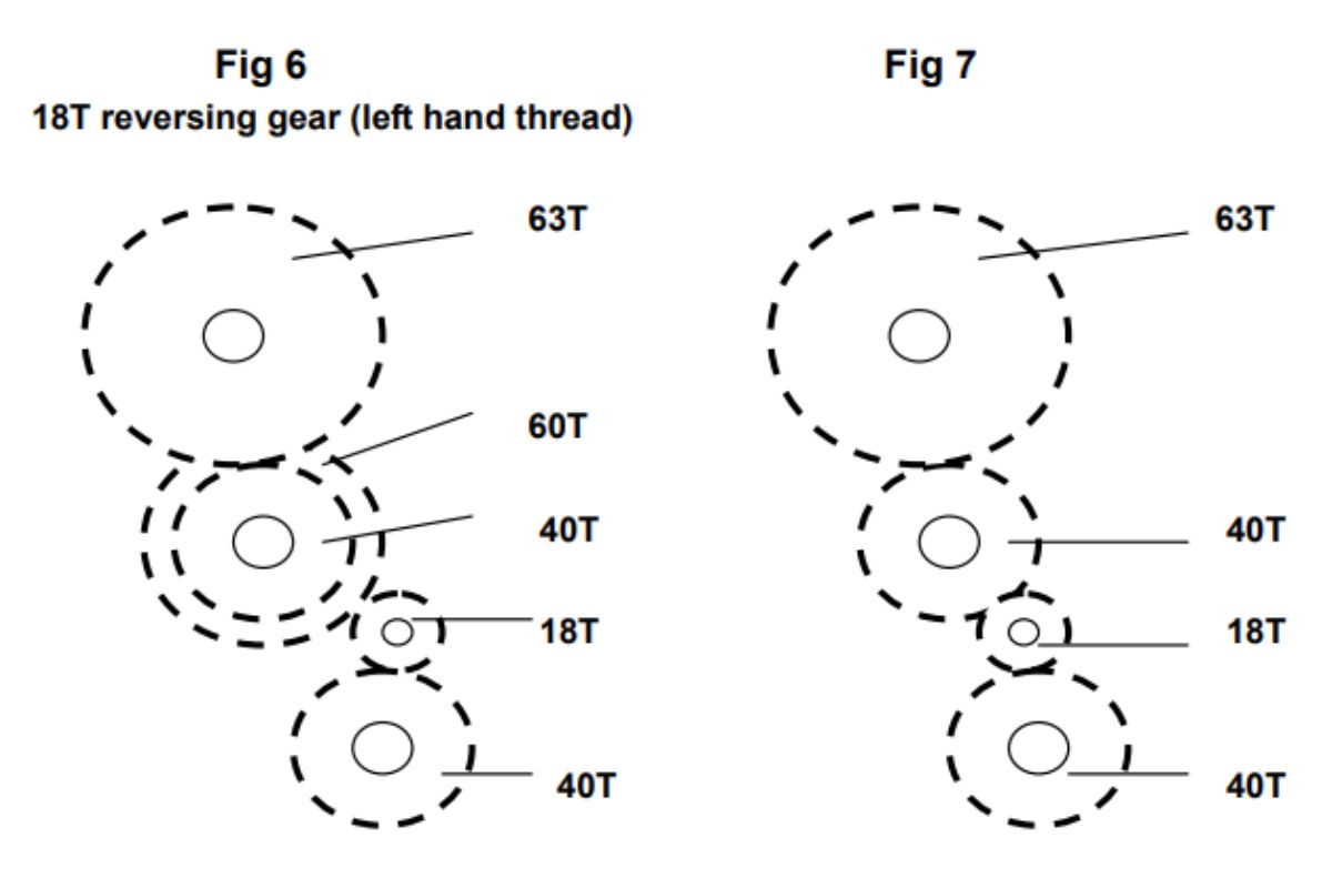
18T reversing gear
The 18T reverse tumbler gear, when fitted, enables the rotation of the leadscrew to be reversed. For left hand threads (as Fig 6) or in the case of an asymmetric change gear selection to allow the leadscrew to maintain its correct rotation.
Oil sight glass
The oil level sight glass enables you to check the amount of oil you have in your gearbox.
Bench Lathe Maintenance
Your ELATHE500 light bench lathe is a precision tool. In order to maintain this precision and prolong its useful life, it is advised that you follow the recommended daily and periodic maintenance tables printed below.
Installation/Commissioning Oil Changing
| Interval | Action |
|---|---|
| 1st oil change | Drain the gearbox and renew the oil after 35hrs. running |
| 2nd oil change | Drain the gearbox and renew after 110hrs. running |
| Thereafter | Drain the gearbox and renew oil after every 300hrs. running |
Daily Pre-Use
Using an oilcan with a narrow nozzle, oil all the oil points on the machine:
- A) Saddle (4)
- B) Tailstock (2)
- C) Traverse slide (1)
- D) Compound slide (2)
- E) Leadscrew gearbox (2)
- F) Leadscrew end bearing (1)
Move the traverse and compound slides to give access to their drive shaft threads and lightly coat with oil, work the oil up the threads to lubricate the thread followers.
Spray-oil the slides and the lathe bed, exercise the saddle and the slides to spread the oil to all surfaces, both hidden and visible.
Spray up under the rack cover to lubricate the rack (G).
Apply oil to the change gears and their axle pins.
Daily Post-Use
- Clean all swarf and chips away from the machine bed, slide surfaces, and the tool post.
- Exercise the slide and ensure no swarf etc., is lodged in the drive shaft tunnels.
- If you have been using 'suds' make sure the machine is thoroughly dried off. Clear the suds tray of all swarf and chips, especially around the drain.
- Check the tool, ensure it is usable the next time, if not re-sharpen or replace the tool tip.
- Lightly oil spray all the machine beds and surfaces, and the tailstock barrel.
- Clean and lightly oil any tools you may have been using (centers, drill chucks, spanners chuck keys etc, and put them away).
- Switch off the power supply. Disconnect the plug.
- Cover the machine over with a dust cover.
Weekly
- a) Check the belt tension
- b) Check the oil level in the gearbox
- c) Check the tautness of the slides
- d) Check the level of the suds reservoir (if you are using coolant)
Recommended Products
| Application | Product |
|---|---|
| Gearbox oil | 15/40w non synthetic (such as GTX White) |
| Grease | rocol saphire 2 (code: ROC 52041) |
| Lubricant | rocol slide way lubricant spray (code: ROC 52041) |
| Cutting fluid | rocol multisol cutting fluid (code: ROC 3521L) |
Oil Lubrication Points
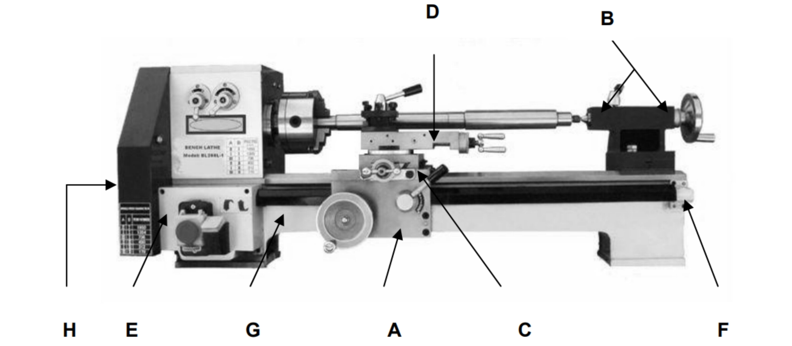
A: Saddle control
B: Tailstock barrel lock
C: Auto-feed lever
D: Compound slide
E: Leadscrew gearbox
F: Leadscrew end bearing
G: Rack (under cover)
H: Change gears
Change Gear Tables
Metric Thread Pitch Gears
| mm | G1 | G2 | G3 | G4 |
|---|---|---|---|---|
| 0.25 | 30 | 50 | - | 80 |
| 0.3 | 45 | 35 | - | 100 |
| 0.35 | 21 | 80 | - | 40 |
| 0.4 | 30 | 65 | - | 50 |
| 0.45 | 45 | 50 | 60 | 80 |
| 0.5 | 30 | 80 | - | 40 |
| 0.6 | 45 | 60 | - | 50 |
| 0.7 | 63 | 45 | - | 60 |
| 0.75 | 45 | 65 | - | 40 |
| 0.8 | 60 | 55 | - | 50 |
| 1.0 | 45 | 80 | - | 30 |
| 1.25 | 45 | 80 | - | 24 |
| 1.5 | 63 | 42 | 60 | 40 |
| 1.75 | 63 | 60 | - | 24 |
| 2.0 | 63 | 65 | - | 21 |
| 2.5 | 45 | 40 | 100 | 30 |
| 3.0 | 63 | 40 | 100 | 35 |
Imperial Thread T.P.I. Gears
| tpi | G1 | G2 | G3 | G4 |
|---|---|---|---|---|
| 48 | 50 | 55 | - | 63 |
| 40 | 60 | 50 | - | 63 |
| 32 | 60 | 63 | 50 | 40 |
| 28 | 60 | 63 | 50 | 35 |
| 26 | 50 | 65 | 80 | 42 |
| 24 | 50 | 63 | 80 | 40 |
| 22 | 50 | 55 | 80 | 42 |
| 20 | 40 | 80 | - | 21 |
| 19 | 60 | 63 | 80 | 38 |
| 18 | 50 | 63 | 80 | 30 |
| 16 | 50 | 80 | - | 21 |
| 14 | 50 | 42 | 80 | 35 |
| 12 | 50 | 60 | 80 | 21 |
| 11 | 50 | 55 | 80 | 21 |
| 10 | 60 | 42 | 80 | 30 |
| 9 | 40 | 45 | 100 | 21 |
| 8 | 60 | 42 | 100 | 30 |
Safety Warnings
General Safety
The following suggestions will enable you to observe good working practices, keep yourself and fellow workers safe and maintain your tools and equipment in good working order.
WARNING! KEEP TOOLS AND EQUIPMENT OUT OF THE REACH OF YOUNG CHILDREN
Mains Powered Tools
These machines are supplied with a moulded 13Amp Plug and 3 core power cable. Before using the machine inspect the cable and the plug to make sure that neither are damaged. If any damage is visible have the machine inspected/repaired by a suitably qualified person. If it is necessary to replace the plug, it is preferable to use an 'unbreakable' type that will resist damage. Only use a 13Amp.
If extension leads are to be used, carry out the same safety checks on them, and ensure that they are correctly rated to safely supply the current that is required for your machine.
Ideally, your lathe should be installed close to a correctly rated power supply, in a warm dry environment, well ventilated and illuminated by bright clear natural light, with adequate access all around the machine, and sufficient adjacent storage space for your tools, accessories and materials.
Key Operating Reminders
- Always stop the spindle before changing gears or direction
- Keep the auto-feed lever engaged during thread cutting to ensure correct "pick-up"
- Do not overfill the headstock—oil will leak from non-sealed bearings
- The saddle control handle turns automatically during auto-feed—this is normal
- Use the reversing switch only when the spindle is completely stopped
- Ensure the change gear compartment door is closed—the machine will not start otherwise
Final Note
This manual provides the complete operational guidance for your ELATHE500 Precision Bench Lathe. Following these procedures will ensure safe operation, consistent accuracy, and long service life from your machine. Keep this manual accessible for all operators and refer to it regularly for maintenance schedules and change gear configurations.